00194440-10_SM_X-Series_Customer_en.pdf - 第147页
Service Work 3.5.6 Replacing the Complete Lever/Toggle [03013445-xx] C&P20 Nozzle Changer Service Manual SIPLACE X Series 147 3.5.6 3 . 5 . 6 R e p la c in g t h e C o m p le t e L e v e r / T o g g le [ 0 3 0 1 3 4 …
Service Work
C&P20 Nozzle Changer 3.5.5 Replacing the Three mm Green LEDs [03021168-xx]
146 Service Manual SIPLACE X Series
3.5.5
3.5.5 Replacing the Three mm Green LEDs [03021168-xx]
Replacing the Three mm Green LEDs [03021168-xx]
Removal/installation
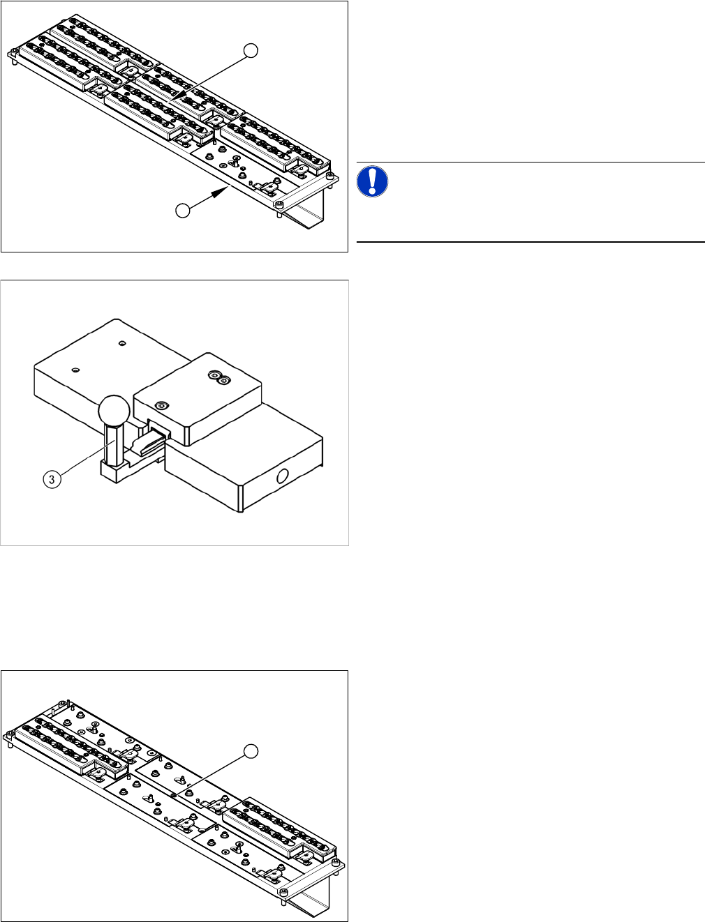
1. C&P20 nozzle changer with a free slot for setting
gauge [03028340-xx]
2. Green diode: shines when status is Nozzle changer
closed.
► Instead of the magazine (for which the microswitches
monitor the positions open/closed), attach the setting
gauge to the free nozzle changer slot (1).
NOTICE!
Make sure that all other nozzle changers are attached to
the nozzle changer!
Setting gauge for C&P20 nozzle changer [03028340-xx]
► Press in the lever (3) of the setting gauge. This sim-
ulates a closed magazine.
► Turn the nozzle changer over and carefully place it
down on the installation location, with the magazines
pointing downwards.
► Make sure you do not touch any electrical connec-
tions.
► Switch the machine on.
► Use the two fastening screws to adjust the micros-
witch, so that the green LED (2) shines.
⇨ This ensures that the microswitch switches cor-
rectly.
► Pull out the lever (3) of the setting gauge. This simu-
lates an open magazine.
⇨ Make sure that the green LED (2) does not shine!
1
2
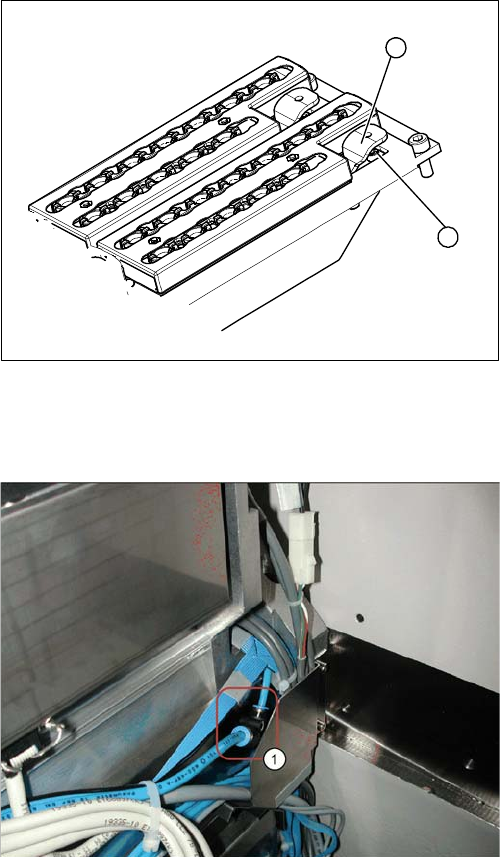
1. Green LED three mm
► Remove the nozzle magazine in the center. The LED
is located beneath (1).
► Remove the cover (2).
► Pull the LED (1) out towards the back.
► Unplug the connection cable.
► Remove the cable ties.
1
Service Work
3.5.6 Replacing the Complete Lever/Toggle [03013445-xx] C&P20 Nozzle Changer
Service Manual SIPLACE X Series 147
3.5.6
3.5.6 Replacing the Complete Lever/Toggle [03013445-xx]
Replacing the Complete Lever/Toggle [03013445-xx]
Removal/installation
3.5.7
3.5.7 Installation and Height Adjustment of Nozzle Station (Description for Docking Unit [03015680-06] with 1-Wire-Hub)
Installation and Height Adjustment of Nozzle Station (Description for Docking Unit
[03015680-06] with 1-Wire-Hub)
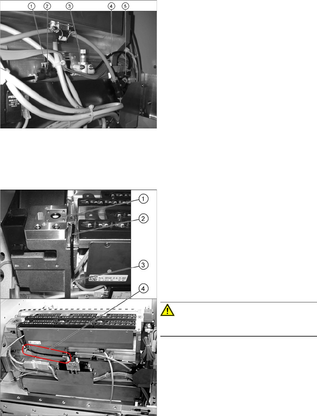
1. Toggle
2. Fastening screw
► Loosen the screw (2) holding the toggle (1).
► Remove the toggle (1), insert a new one and fix this
with the fastening screw (2).
1
2
1. T-piece on component trolley feed device
► Disconnect the pneumatic hose from the COT insert.
Service Work
C&P20 Nozzle Changer 3.5.7 Installation and Height Adjustment of Nozzle Station (Description for
148 Service Manual SIPLACE X Series
1. Dummy plugs
2. Throttle valve
3. Fine throttle
4. Hose
5. T-piece press-fit connection QSMT-4
► Use the T-piece and PUN hose from the component
trolley feed device to connect the T-piece "press-fit
connection QSMT-4" [03046434-xx] (5) with the
PUN-CM 4x0.75 40 mm [03046289-xx].
► Fit the "Fine throttle GRO-QS-4-LF"
[03045754-xx] (3) with the screws "DIN912 M3x18 -
A2-70" [03045034-xx] onto the "holding plate for
throttle" [03046270-xx] and then fix all this to the tape
feed channel with the screws "DIN7981 ST3.5x6.5-C-
H-A2" [03046777-01] (see photo).
► Remove the "Plug QSC-4H" [00330249-xx] for set-
ting the air blast (see photo).
► Use the two T-pieces to connect the throttle valve
with the "PUN-CM 4x0.75 70 mm" - hoses
[03046291-xx].
1. Nozzle station
2. Hose PUN-CM 4x0.75 420 mm
3. Cable clamp
4. Hose run correctly
► Fit the nozzle station [03045404-xx] (1) with the two
screws "DIN7991 M4x20 - 8.8" [00333782-xx].
► Run the long hose "PUN-CM 4x0.75 420 mm"
[03046432-xx] (2) up to the T-piece (see photo).
► Secure this hose with a cable clamp "Clamp Panduit
CC S12-S08 D3.1 b 8.2" [00368063-xx] (3) and a
screw "DIN912 M3x6 - A2-70" [03045028-xx].
CAUTION!
Make sure that the hose is run in front of the holding plate
for the 1-wire hub (4).