00194440-10_SM_X-Series_Customer_en.pdf - 第217页
Service Work 3.9.4 Replacing the Control Unit Cutter Service Manual SIPLACE X Series 217 3.9.4 3 . 9 . 4 R e p la c in g t h e C o n t r o l U n it Replacing the Control Unit To replace a contr ol unit [03006411- xx] wit…
Service Work
Cutter 3.9.3 Replacing the Articulated Joint on the Short-Stroke Cylinder [03000518-xx]
216 Service Manual SIPLACE X Series
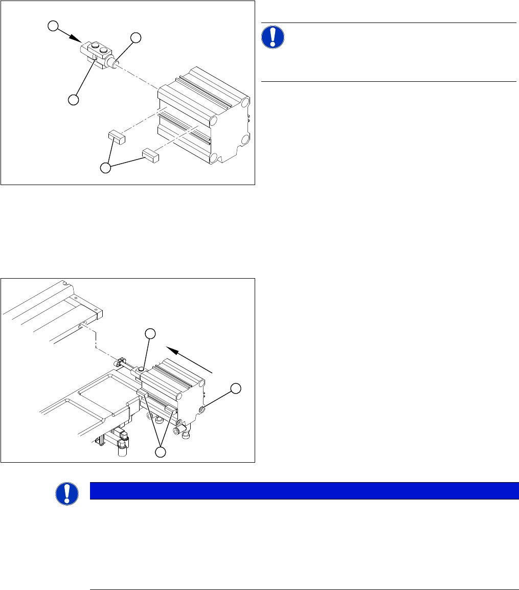
Installing the articulated joint
► Unscrew the articulated joint (1) from the cylinder.
NOTICE!
The threaded pin is secured with Loctite no 241. You will
need somewhat more strength than usual to loosen it.
► Apply a small amount of Loctite no. 241 to the thread
(2) of the new joint.
► Screw the articulated joint (1) into the short-stroke
cylinder.
► Turn the articulated joint in its installation position (3).
Once the cylinder is installed, the slot in the moveable
blade prevents the articulated joint from turning.
► Copy the exact installation position of the proximity
switch (4) onto the new short-stroke cylinder (e.g.
with a feeler gauge, fine-tipped marker pen).
1
4
3
2
► Install the proximity switch (1) precisely in the position
you marked with the permanent marker.
► Place the prepared cylinder into the cutter, in the cor-
rect rotary position of the articulated joint (2).
► Fasten the cylinder in this position, with the two
screws provided (3).
► Connect the compressed air hoses to the cylinder in
the correct allocation.
► Check the gap between the leading edge of the tape
deflector and the "empty-tape baffle, inside".
► Check the switching points of the proximity switches.
1
3
2
NOTICE
If the tapes are not cut correctly.
If the tapes are not cut correctly, even though the switching points have been set properly and
the short-stroke cylinder has been exchanged - complete with the one-way restrictor - the cause
of the problem may be:
► Incorrect compressed air level
► Leaking compressed air connection or Y-socket union
Service Work
3.9.4 Replacing the Control Unit Cutter
Service Manual SIPLACE X Series 217
3.9.4
3.9.4 Replacing the Control Unit
Replacing the Control Unit
To replace a control unit [03006411-xx] with a control unit of identical design, follow the instructions at:
"3.9.4.1 Replacing the Control Unit [03006411-xx]" [ ➙ 217]
To replace a control unit [03006411-xx] with a "CAN node NC tape cutter X/HF" [03052927-xx] follow
the instructions at:
"3.9.4.2 Replacing the Control Unit "CAN Nodes NC Tape Cutter X/HF" [03052927-xx]" [ ➙ 218]
See also
6.4.1 Control Unit on Cutter [ ➙ 376]
6.4.2 Control Unit on Cutter (CAN Nodes) [ ➙ 377]
3.9.4.1
3.9.4.1 Replacing the Control Unit [03006411-xx]
Replacing the Control Unit [03006411-xx]
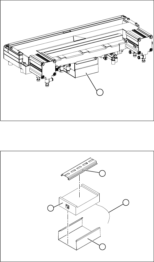
Overview
Removal/installation
1. Control unit under the cover
► Remove the cover (1) from the control unit.
1
► Mark the allocation of all press-fit connections and
disconnect all press-fit connections (2) from the con-
trol unit.
► Remove the cable ties and the connection cable fix-
tures.
► Carefully pull the control unit (3) off of its mount (4).
► Carefully insert the new control unit onto the mount,
in the correct rotary position and location, until it locks
into place.
► Restore all plug-and socket connections in the cor-
rect allocation.
► Run the connection cables and fasten with cable ties
(strain relief).
► Replace the control unit cover.
1
4
3
2
Service Work
Cutter 3.9.4 Replacing the Control Unit
218 Service Manual SIPLACE X Series
3.9.4.2
3.9.4.2 Replacing the Control Unit "CAN Nodes NC Tape Cutter X/HF" [03052927-xx]
Replacing the Control Unit "CAN Nodes NC Tape Cutter X/HF" [03052927-xx]
The control unit [03006411-xx] is replaced with a "CAN Nodes NC Tape Cutter X/HF" [03052927-xx].
General
The "CAN nodes NC tape cutter" module assumes the following tasks:
1. Cutter control (see Chapter Component Handling)
2. Nozzle changer control (row 1/2)
3. Valve control in the nozzle station
4. Sensor monitoring at the component and nozzle reject bin
The "CAN nodes NC tape cutter" is backwards compatible with the old tape cutter boards. This assem-
bly can therefore be used in X, HF and D series machines.
However, the nozzle station function (air blast valve C&P20A head) and the sensors for the reject con-
tainer CO/nozzles are not supported. The CAN nodes therefore need to be set accordingly via the jump-
ers. (See "6.4.2 Control Unit on Cutter (CAN Nodes)" [ ➙ 377].)
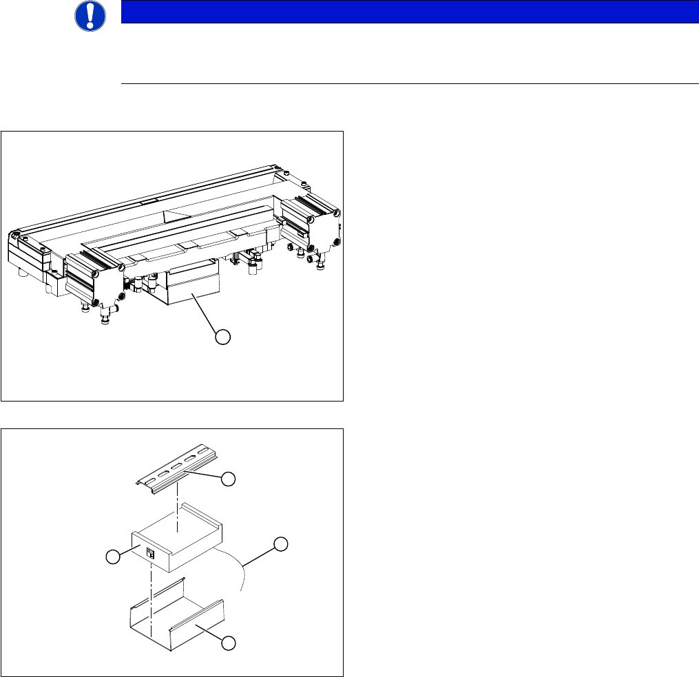
Removal/installation
NOTICE
Control via CAN nodes
Old nozzle changers, which were addressed via the one wire bus, are not able to communicate
via the CAN nodes. The new NC can be addressed via the one wire bus and CAN nodes.
1. Control unit under the cover
► Remove the cover (1) from the control unit.
► Mark the allocation of all press-fit connections and
disconnect all press-fit connections (2) from the con-
trol unit.
► Remove the cable ties and the connection cable fix-
tures.
► Carefully pull the control unit (3) off of its mount (4).
► Carefully insert the new control unit onto the mount,
in the correct rotary position and location, until it locks
into place.
► Restore all plug-and socket connections in the cor-
rect allocation.
► Run the connection cables and fasten with cable ties
(strain relief).
► Replace the control unit cover.
1
1
4
3
2