00194440-10_SM_X-Series_Customer_en.pdf - 第296页
Settings Axis Control 5.2.4 C&P20 296 Service Manua l SIPLACE X Series 5.2.4.3 5 . 2 . 4 . 3 S t a r A x is C o n t r o l S y s t e m Star Axis Control System Checking the Star Axis Dynamics Star axis contro l for C&…
Settings
5.2.4 C&P20 Axis Control
Service Manual SIPLACE X Series 295
5.2.4.2
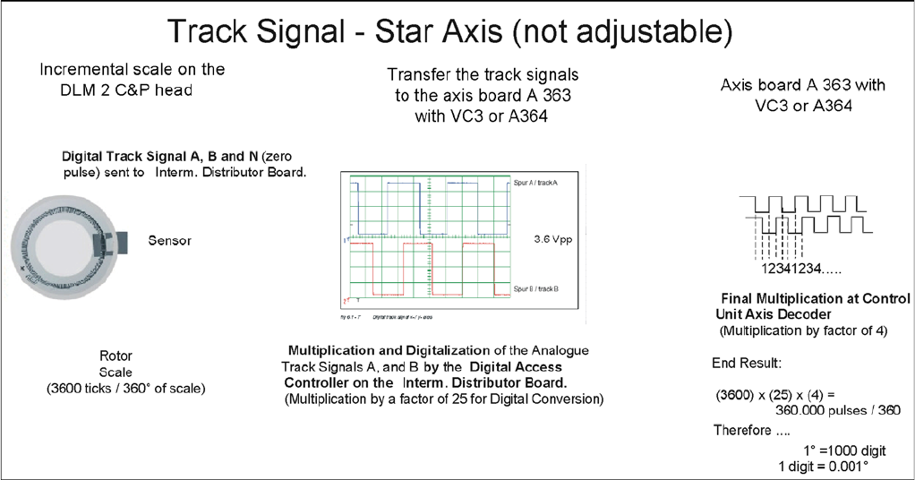
5.2.4.2 Track Signals for Head Axes
Track Signals for Head Axes
The track signals play a greater role with the new drive concept for X (HF) machines. They are respon-
sible for the exactly and precise positioning of the axes and are used as the only feedback signal in the
closed-loop control system, meaning that they have an important influence on the axis dynamics.
Preparing the Track Signals
Settings
Axis Control 5.2.4 C&P20
296 Service Manual SIPLACE X Series
5.2.4.3
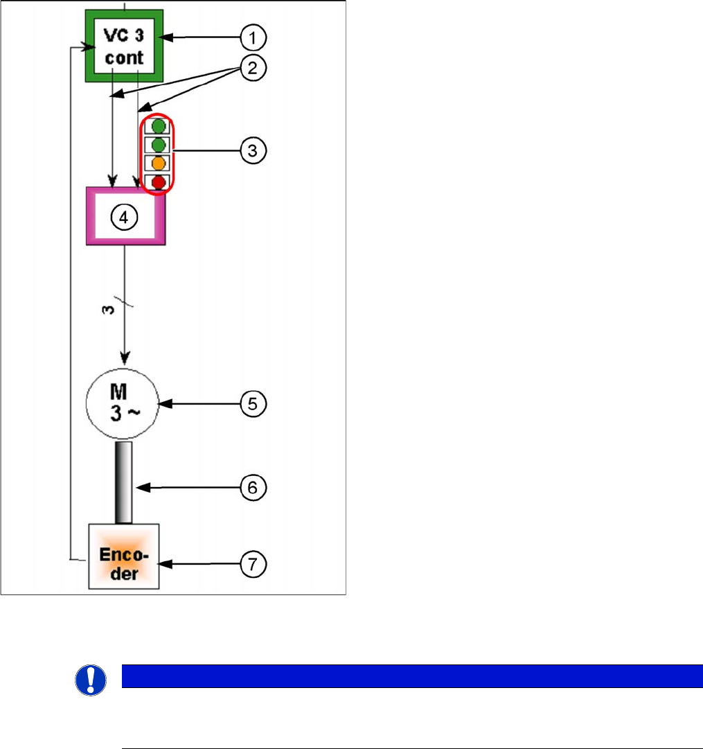
5.2.4.3 Star Axis Control System
Star Axis Control System
Checking the Star Axis Dynamics
Star axis control for C&P6/12/20
The star axis is driven via a 3-phase AC stepping motor
with an intermediate circuit voltage of 120 V. The activa-
tion is via two track signals (phase shift 120°) from the
VC3 controller Itarget "W" and I-target "U". The third
phase is calculated automatically.
1. Axis controller board A363 with VC3 controller (VC =
Velocity Commutation) or A 364
2. Control signals
3. LEDs on servo amplifier:
4. Servo amplifier
5. 3 phase AC motor.
6. Between the motor and the incremental encoder
there is a fixed mechanical connection.
7. Read unit: transmits the exact position of the axis
(track signals).
The servo board controls the 3-phase AC motor directly.
NOTICE
Machine at operating temperature
Before checking the axis dynamics, make sure that the machine has reached its operating tem-
perature. Switch the machine on at least 30 minutes before you begin work.
Settings
5.2.4 C&P20 Axis Control
Service Manual SIPLACE X Series 297
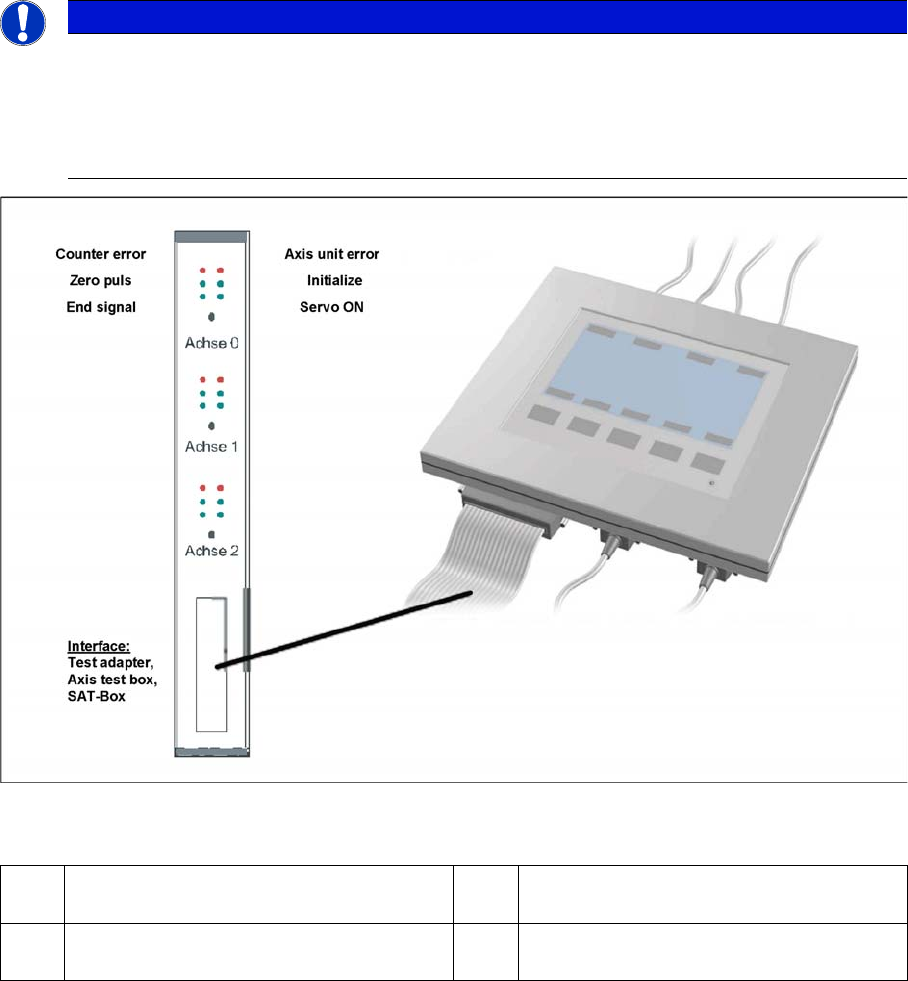
Measurement Setup with SAT Box and A363
Measurement setup with SAT box
Assignment of output leads by the SIPLACE Axis tester (SAT) and connection to the oscilloscope.
NOTICE
Dynamic check
When checking the dynamics, it may be sufficient if you check the travel times and overshoot
behavior of the axis with the SIPLACE axis tester display and the values in the settings tables.
► However, when checking for errors, you will need to use a suitable oscilloscope for the dy-
namics analysis.
1 The Vnom. output signal is currently not
needed for checking X (HF) dynamics.
3 Position deviation connected at CH1
2 Uncommutated current signal (Vreg), con-
nected to CH2
4 End position signal connected at CH3