00194440-10_SM_X-Series_Customer_en.pdf - 第232页
Service Work Component Trolley HF R2 3.11.1 Replacing the Fixed/Guide Castor s [00341918-xx] 232 Service Manua l SIPLACE X Series 3.11 3 . 1 1 C o m p o n e n t T r o lle y H F R 2 Component Trolley HF R2 3.11.1 3 . 1 1 …
Service Work
3.10.6 Replacing the Actuator/Protective Bracket X-Series Component Trolley
Service Manual SIPLACE X Series 231
3.10.6
3.10.6 Replacing the Actuator/Protective Bracket
Replacing the Actuator/Protective Bracket
Parts, equipment and tools
▪ Torque wrench T20 with drilled hole (for screw ISO 7380-TX with pin - M4)
▪ Actuator AZ335 Schmersal [03013488-xx]
▪ Protective bracket: holder and protection for actuator [03095447-xx]
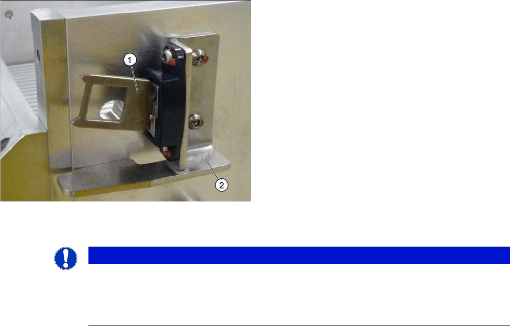
Overview
Installation
1. Actuator
2. Protective bracket
NOTICE
Installation instructions
► Tighten the fastening screws for the actuator on the protective bracket with amaximum
torque of 200 Ncm.
► Set the actuator (see "5.5.1 Setting the Actuator on the Component Trolley" [ ➙ 347]).
Service Work
Component Trolley HF R2 3.11.1 Replacing the Fixed/Guide Castors [00341918-xx]
232 Service Manual SIPLACE X Series
3.11
3.11 Component Trolley HF R2
Component Trolley HF R2
3.11.1
3.11.1 Replacing the Fixed/Guide Castors [00341918-xx]
Replacing the Fixed/Guide Castors [00341918-xx]
Parts
▪ Fixed castor (00341918-xx)
▪ Guide castor (03004958-xx]
Removal/installation
3.11.2
3.11.2 Replacing the Cable Tree and ODU Connector [03021249-xx]
Replacing the Cable Tree and ODU Connector [03021249-xx]
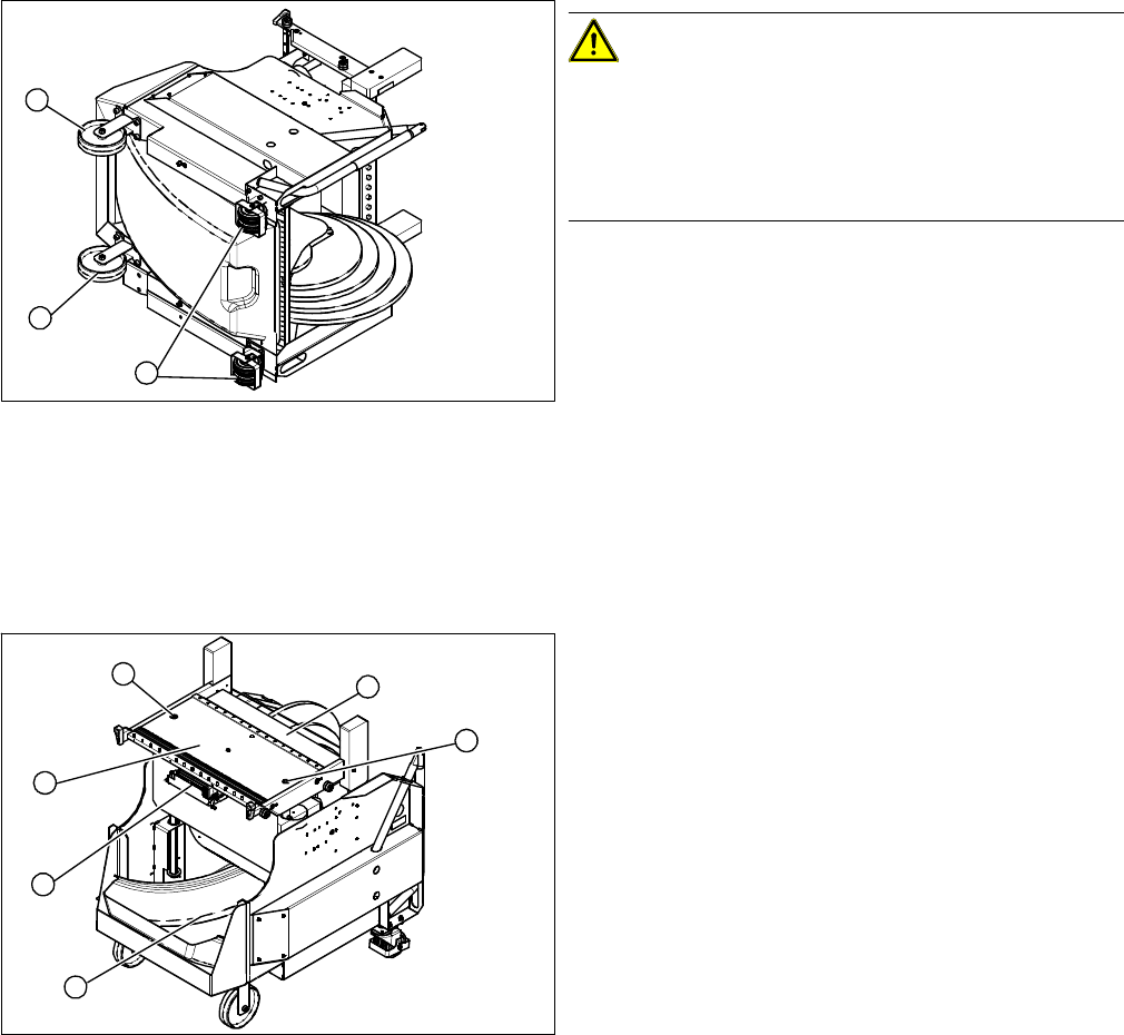
Overview
CAUTION!
Heavy machine part!
The component trolley must be placed on one side in or-
der to remove the fixed/guide castors. The component
changeover table is extremely heavy! You will need 2
people to perform this task.
► Move the component trolley out of the machine.
► Place the component trolley on its side, on a suitable
surface.
► Loosen the fastening screw on the fixed (1) or guide
castor (2) to be replaced.
► Insert the new fixed/guide castor.
► Stand the component trolley on its wheels again.
1
2
1
1. ODU connector with cable tree
2. Feeder Controller Unit
► Move the component trolley out of the machine.
► Loosen the two screws (3) fastening the table plate
(4).
► Remove the waste tape container (5).
► Remove the guidance rods from the height adjust-
ment system.
► Fix the table plate in its highest position. This will help
you to reach the cables more easily.
► Disconnect the ground cable from the frame and from
the component trolley table.
3
5
1
4
3
2
Service Work
3.11.3 Replacing the Table Plate [03020457-xx] Component Trolley HF R2
Service Manual SIPLACE X Series 233
Removal/installation
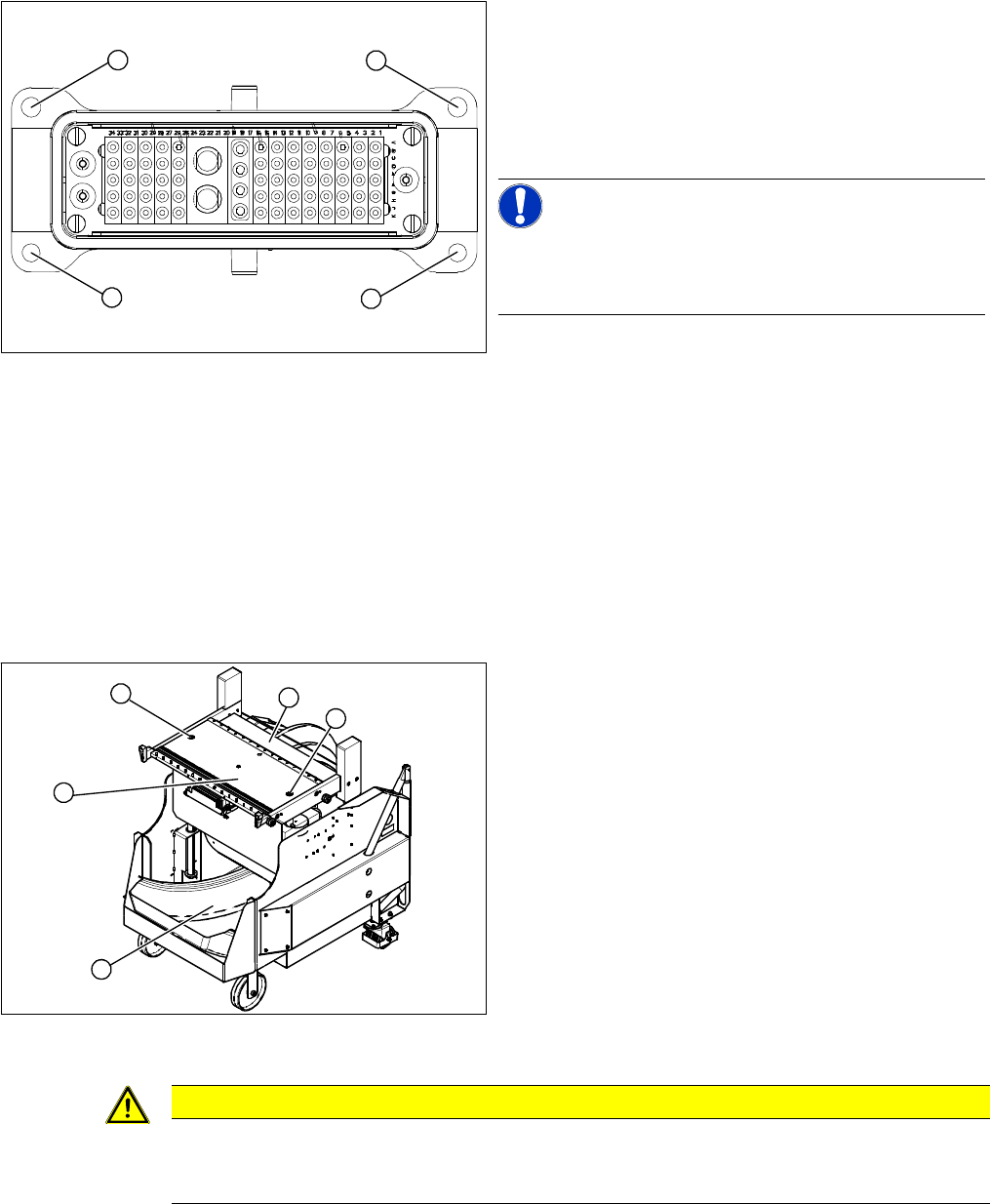
► Thread the connection cables for the new ODU connector through the hole provided.
► Reconnect the feeder control unit to the electrical system.
► Reconnect the compressed air system and the ground cable.
► Fasten the ODU connector with the fitting screws (1) at the top and with the fastening screws (2) at
the bottom.
3.11.3
3.11.3 Replacing the Table Plate [03020457-xx]
Replacing the Table Plate [03020457-xx]
Removal/installation
► Lift the table plate out of the component trolley.
► Lift the new table plate into the component trolley.
► Reconnect the compressed air system and the ground cable.
► Fit the table plate with the two fastening screws and the guidance rods.
Secure the two fastening screws with Loctite 243.
► Loosen the top fitting screws (1) on the ODU connec-
tor.
► Loosen the bottom fastening screws (2) and remove
the ODU connector.
► Disconnect the connection cable from the back of the
feeder control unit.
NOTICE!
The cable for the option "Splice Detection" is already in-
tegrated into the cable tree and is run in a bundle under
the table.
► Disconnect from the compressed air system.
1
1
2
2
► Move the component trolley out of the machine.
► Remove the waste tape container (4).
► Dismantle the feeder control unit (3).
► Remove the two screws (1) fastening the guide rods
to the table plate (2).
► Remove the guidance rods from the height adjust-
ment system.
► Unplug the ground cable and the compressed air sys-
tem from the underside of the table.
1
3
4
1
2
CAUTION
Heavy machine part!
The table plate is heavy (approx. 29 kg). You will need to enlist the help of a second strong
person to help you lift it out.