00194440-10_SM_X-Series_Customer_en.pdf - 第51页
Service Work 3.1.1 Measuring Voltages at the Power Supply Unit [00354626-xx] Electrics and Control Service Manual SIPLACE X Series 51 Power supply at the front end 2 Measuring voltages (*) Accord ing to the c usto mer ne…
Service Work
Electrics and Control 3.1.1 Measuring Voltages at the Power Supply Unit [00354626-xx]
50 Service Manual SIPLACE X Series
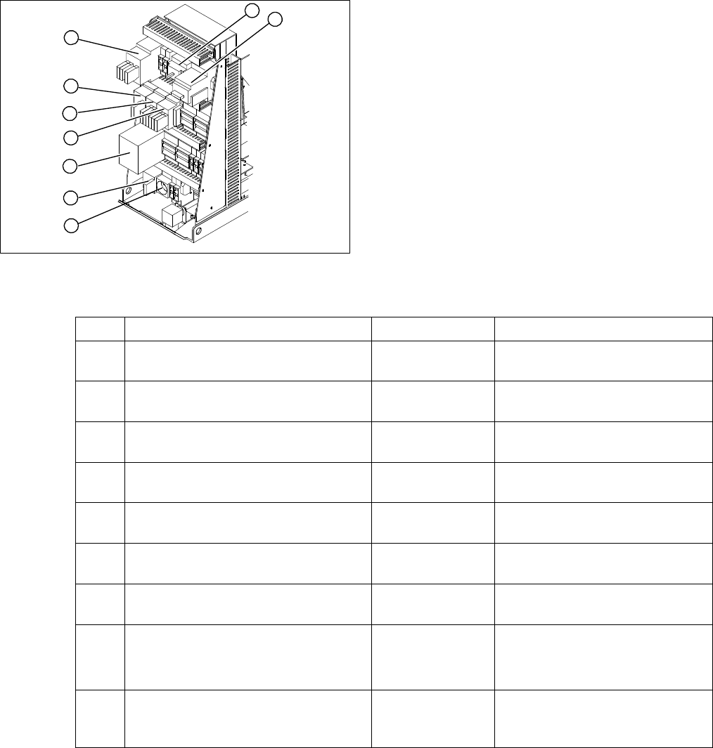
Power supply at the front end 1
Measuring voltages
(*) According to the customer network supply voltage
1. Service socket X102
2. Main switch Q1
3. Motor circuit breaker Q2
4. Main contactor K1
5. Contactor K 2
6. Contactor K 3
7. Contactor K 4
8. Protective contactor combination K6
9. Contactor K 5
1
9
8
7
6
5
4
3
2
Item Designation Contacts Voltage
1 Service socket X102 115 VAC / 220 VAC /
230 VAC 240 VAC (*)
2 Main switch Q1 1, 3, 5 and
2, 4, 6
3 x 204 VAC / 3 x 380 VAC
3 x 400 VAC / 3 x 415 VAC (*)
3 Motor circuit breaker Q2 1, 3, 5 and
2, 4, 6
3 x 204 VAC / 3 x 380 VAC
3 x 400 VAC / 3 x 415 VAC (*)
4 Contactor K 1 1, 3, 5 and
2, 4, 6
3 x 204 VAC / 3 x 380 VAC
3 x 400 VAC / 3 x 415 VAC (*)
5 Contactor K 2 1, 3, 5 and
2, 4, 6
3 x 177 VAC
6 Contactor K 3 1, 3, 5 and
2, 4, 6
3 x 177 VAC
7 Contactor K 4 1, 3, 5 and
2, 4, 6
3 x 177 VAC
8 Protective contactor combination K6 L+, X1,X3, X5
13, 33
23
24 V DC against ground
24 V DC against ground
32 V DC against ground
9 Contactor K 5 A1 (+) to A2 (-)
1, 3, 7
2, 4, 8
24 VDC
24 V DC against ground
24 V DC against ground
Service Work
3.1.1 Measuring Voltages at the Power Supply Unit [00354626-xx] Electrics and Control
Service Manual SIPLACE X Series 51
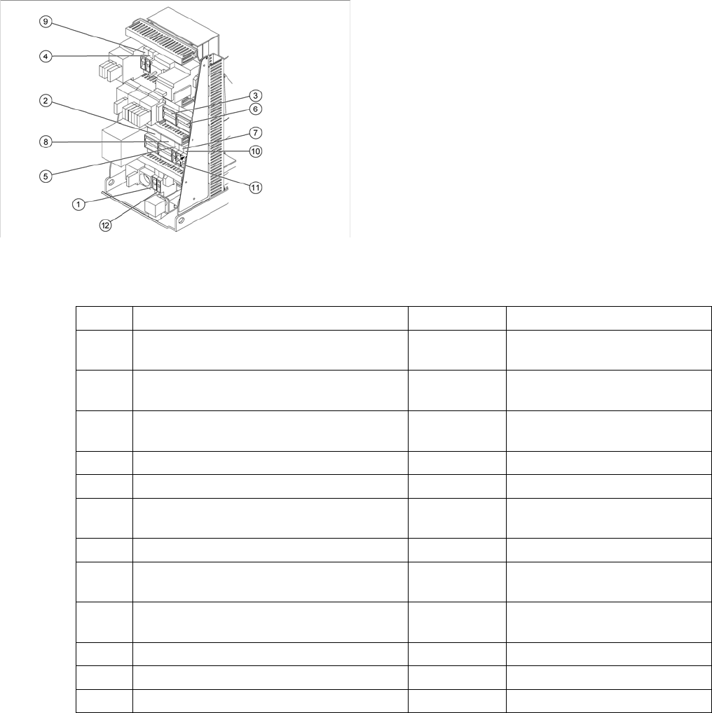
Power supply at the front end 2
Measuring voltages
(*) According to the customer network supply voltage
1. Fuse F1
2. Fuse F2
3. Fuse F4
4. Fuse F5
5. Fuse F6
6. Fuse F7
7. Fuse F8
8. Fuse F10
9. Fuse F11
10. Fuse F12
11. Fuse F13
12. Fuse F14
Item Designation Contacts Voltage
1 Fuse F1 for service socket (6A) 1, 2 115 VAC / 220 VAC
230 VAC / 240 VAC (*)
2 Fuse F2 Component changeover table
(32A)
1, 3, 5 and
2, 4, 6
3 x 36 VAC
3 Fuse F4 X/Y axis (32A) 1, 3, 5 and
2, 4, 6
3 x 177 VAC
4 Fuse F5 Star axis (10A) 1, 2 145 V DC against ground
5 Fuse F6 Z and DP axis, DP for C&P20 (10) 1, 2 39 V DC against ground
6 Fuse F7 Secondary circuit (6A) 1, 3, 5 and
2, 4, 6
3 x 230 VAC
7 Fuse F8 PCB conveyor (6A) 1, 2 33 V DC against ground
8 Fuse F10 Rectifiers U7 and U70 (16A) 1, 3, 5 and
2, 4, 6
3 x 39 VAC
9 Fuse F11 Inrush current limitation board
(1A)
1, 2 33.6 V DC against ground
10 Fuse F12 Illumination (6A) 1, 2 52 V DC against ground
11 Fuse F13 Monitor (3A) 1, 2 26 V DC against ground
12 Fuse F14 Fan Y motor (6A) 1, 2 26 V DC against ground
Service Work
Electrics and Control 3.1.2 Configuring the Input Voltage at the Inrush Current Limitation Board
52 Service Manual SIPLACE X Series
Power supply at the side
Measuring voltages
(*) According to the customer network supply voltage
3.1.2
3.1.2 Configuring the Input Voltage at the Inrush Current Limitation Board
Configuring the Input Voltage at the Inrush Current Limitation Board
1. Terminal panel X100
2. Rectifier U1 to U11
3. Line filter
4. Inrush current limitation board
5. DC/DC converter 24 V (behind the cover)
6. DC/DC converter 5V/24V (behind the cover)
7. Position of fuses F21 to F142
6
5
7
4
3
2
1
Item Designation Contacts Voltage
1 Terminal panel X100 L1, L2, L3 3 x 204 VAC / 3 x 380 VAC
3 x 400 VAC / 3 x 415 VAC (*)
Micro fuse F21, F22, F23 (T 6A, 3A) dis-
charge throttle L20
1, 2 3 x 204 VAC / 3 x 380 VAC
3 x 400 VAC / 3 x 415 VAC
Fuse F61, F62 Rectifier U4 1, 2 3 x 28 VAC
Microfuse F81, F82 (T 10A)
Rectifier U5
1, 2 3 x 23.8 VAC
Micro fuse F111, F112 (T 1A)
Rectifier U8
1, 2 3 x 23.8 VAC
Micro fuse F131, F132 (T 4A)
Rectifier U10
1, 2 3 x 19.7 VAC
Micro fuse 141, F142 (T 6A, 3A)
Rectifier U11
1, 2 3 x 18.7 VAC
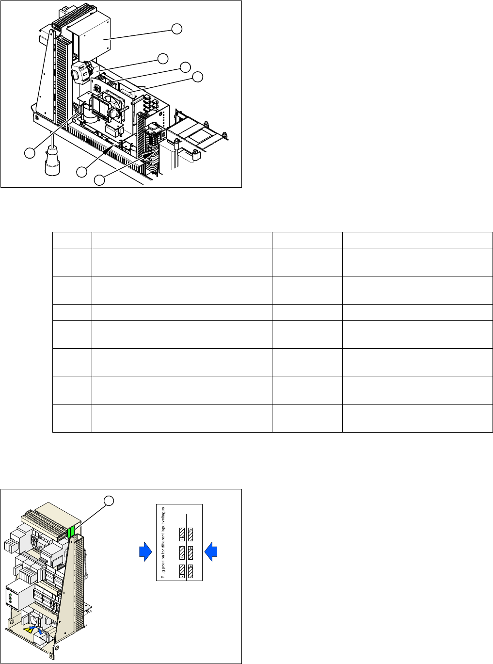
1. Inrush current limitation board
X1, X2, X3: plug-in jumpers to configure the inrush cur-
rent limitation
The inrush current limitation board must be configured in
line with the supply voltage. This is performed with the
help of plug-in jumpers on the inrush current limitation
board (1).
► Check the jumper arrangement and correct if neces-
sary.
Take note of the position of jumper J1 (see "6.1.1 In-
rush Current Limitation Board Transformer (A1)
[03066830-xx]" [ ➙ 363]).
X1
X2
X1
X2
X3X3
400 230
Input voltage
3 x 380 V~
3 x 400 V~
3 x 415 V~
3 x 204 V~
3 x 230 V~
1