00194440-10_SM_X-Series_Customer_en.pdf - 第194页
Service Work Modular PCB Conveyor System 3.6.22 Overview of the Electrical Co mponents 194 Service Manua l SIPLACE X Series 3.6.22.6 3 . 6 . 2 2 . 6 E x t e n s io n C o n t r o lle r B o a r d T S P 3 0 1 E f o r D u a …
Service Work
3.6.22 Overview of the Electrical Components Modular PCB Conveyor System
Service Manual SIPLACE X Series 193
3.6.22.4
3.6.22.4 Lifting Table Conversion Board [00362766-xx]
Lifting Table Conversion Board [00362766-xx]
Overview
3.6.22.5
3.6.22.5 Conveyor Control TSP 301 [00370397-xx]
Conveyor Control TSP 301 [00370397-xx]
Overview
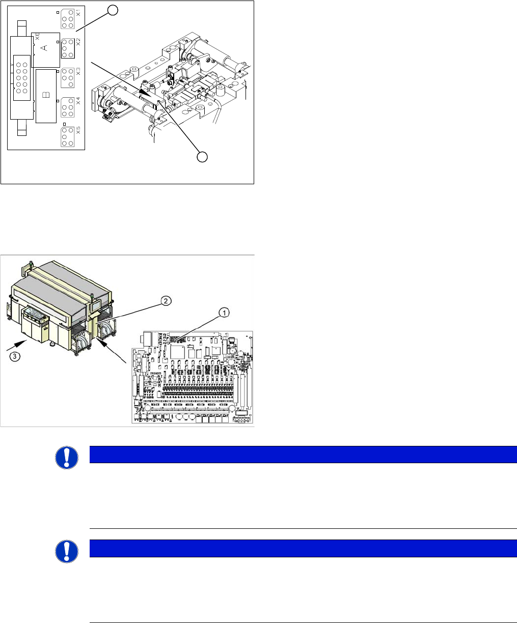
1. Lifting table conversion board
2. Cover
The lifting table conversion board (1) is situated on the
lifting table unit, under the cover (2).
For terminal assignment details, please refer to the cur-
rent version of the circuit diagram folder.
1
2
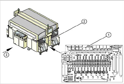
1. Conveyor Control TSP 301
2. Access to conveyor control
3. Transport direction
The TSP 301 conveyor control (1) is situated on the right
side of the middle section of the machine (2) (together
with the pneumatic unit). The conveyor control is secured
with a lockable door.
For terminal assignment details, please refer to the cur-
rent version of the circuit diagram folder for the relevant
machine.
NOTICE
MA data on station computer
The current MA data are saved on the TSP (conveyor control).
► The machine data for the conveyor is saved with the other data in the SW70x.
► SW 60x: Perform a backup of this data at the station computer, at C:\Srcma.
NOTICE
MA data on station computer
The current MA data are saved on the TSP (conveyor control).
► Perform backup of this data at the station computer, at C:\Srcma.
► When replacing the TSP (conveyor), this data can be then be recovered (via SITEST).
Service Work
Modular PCB Conveyor System 3.6.22 Overview of the Electrical Components
194 Service Manual SIPLACE X Series
3.6.22.6
3.6.22.6 Extension Controller Board TSP 301E for Dual Conveyors [00370398-xx]
Extension Controller Board TSP 301E for Dual Conveyors [00370398-xx]
Overview
1. Conveyor control TSP 301E
2. Access to conveyor control
3. Transport direction
The extension board TSP 301E, for dual conveyors, (1)
is situated on the right side of the middle section of the
machine (2), together with the TSP 301 conveyor control.
The conveyor control is secured with a lockable door.
For terminal assignment details, please refer to the cur-
rent version of the circuit diagram folder.
Service Work
3.7.1 Replacing the X-Series COT Insert [03015680-xx] X-Series COT Insert
Service Manual SIPLACE X Series 195
3.7
3.7 X-Series COT Insert
X-Series COT Insert
3.7.1
3.7.1 Replacing the X-Series COT Insert [03015680-xx]
Replacing the X-Series COT Insert [03015680-xx]
Equipment required
▪ Fit-up aid [03015976-xx]
▪ Suitable lifting device (e.g. hand-operated crane)
Overview
Removal/installation
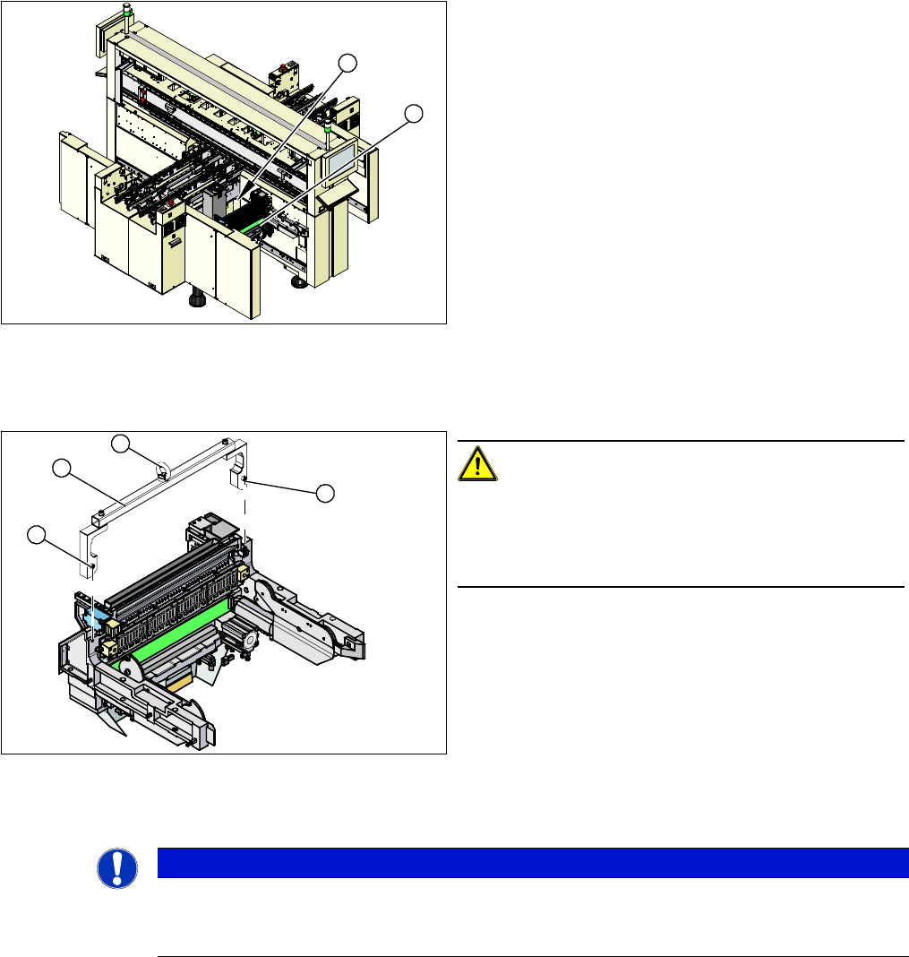
► Attach the fit-up aid (2) to the fixtures provided (1) on the COT insert.
► Fix the lifting device to the eyelet (3) of the fit-up aid (2).
1. COT insert assembly
2. Connection cables and hoses
► The connection cables and hoses (2) are located be-
hind the COT insert – in the space leading to the ma-
chine base (under the nozzle changer).
► Dismantle the nozzle changer.
► Mark the allocation of all press-fit connections so that
you can restore the connections later, with the new
cables.
⇨ Use the detailed circuit diagrams provided with the
machine to help you.
► Unplug all connectors and hoses connected to the
COT insert.
1
2
CAUTION!
Heavy machine part!
The COT insert is heavy. To lift it out, you will need to use
the fit-up aid and a suitable lifting device (hand-operated
crane etc.).
1. Fixtures
2. Fit-up aid
3. Eyelet
1
1
3
2
NOTICE
Marking the position
The COT insert can be installed at different positions in the machine location. Mark the position
of your COT insert, to ensure that this is subsequently returned to its original position.