00194440-10_SM_X-Series_Customer_en.pdf - 第240页
Service Work Docking Station for X-Series C omponent Trolley 3.12.6 Replacing th e 40-Fold Feeder Unlock Device [03011582- xx] 240 Service Manua l SIPLACE X Series Installation ► Loosely screw in the n ew position end sw…
Service Work
3.12.5 Replacing the Positions End Switch of the Component Trolley Locking Device [03033395-XX] Docking Station for X-Series Component
Service Manual SIPLACE X Series 239
3.12.5
3.12.5 Replacing the Positions End Switch of the Component Trolley Locking Device [03033395-XX]
Replacing the Positions End Switch of the Component Trolley Locking Device
[03033395-XX]
Parts, equipment and tools
▪ Position end switch [03033395-xx]
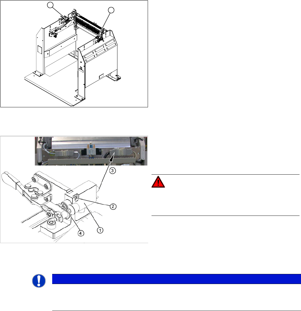
Overview
Removal
► Loosen the two screws fastening the limit switch.
► Open the casing of the connector at the back and label the terminal connections.
► Disconnect the connection cable for the relevant position end switch, in the connector.
► Unthread the connection cable and remove the position end switch.
1. Position end switch – on the left side
2. Position end switch – on the right side
1
2
1. Position end switch with connection cable
2. Two fastening screws
3. Connection cable to connector unit
4. Actuation by locking lever
DANGER!
Switch off the voltage supply
Press the ON/OFF button to switch off and disconnect the
power supply.
NOTICE
Connector for left and right position end switch
► The connection cables for the left and right position end switch are connected to a common
connector.
Service Work
Docking Station for X-Series Component Trolley 3.12.6 Replacing the 40-Fold Feeder Unlock Device [03011582-xx]
240 Service Manual SIPLACE X Series
Installation
► Loosely screw in the new position end switch.
► Run the connection cable to the connector.
► Reconnect the connection cable and close the connector casing.
► Align the position end switch so that the locking lever actuator switches properly.
► Tighten the fastening screws.
► Connect the power pack connection cable and press the ON/OFF button to switch on.
► Check the position end switch function, by trying out the locking procedure.
3.12.6
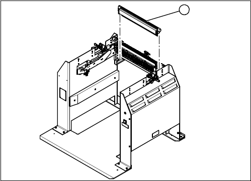
3.12.6 Replacing the 40-Fold Feeder Unlock Device [03011582-xx]
Replacing the 40-Fold Feeder Unlock Device [03011582-xx]
Parts, equipment and tools
▪ Feeder unlocking device 40-fold [03011582-XX]
Overview
Removal/installation
The 40-fold feeder unlock device is the same assembly used in the COT insert. The service work is iden-
tical with the procedure used for the COT insert. All necessary service work is described there.
See also
3.7.3 Replacing the 40-Fold Feeder Unlock Device [03011582-xx] [ ➙ 198]
1. 40 fold feeder unlock device
1
Service Work
3.12.7 Replacing the Feeder Control Unit (FCU) [03059623-xx] Docking Station for X-Series Component Trolley
Service Manual SIPLACE X Series 241
3.12.7
3.12.7 Replacing the Feeder Control Unit (FCU) [03059623-xx]
Replacing the Feeder Control Unit (FCU) [03059623-xx]
Parts, equipment and tools
▪ X-FCU, X-Series [03059623-xx]
Overview
Removal/installation
Removal and installation is identical to that for the COT insert.
See also
3.7.2 Replacing the X Series Feeder Control Unit (FCU) [03020068-xx] [ ➙ 197]
3.12.8
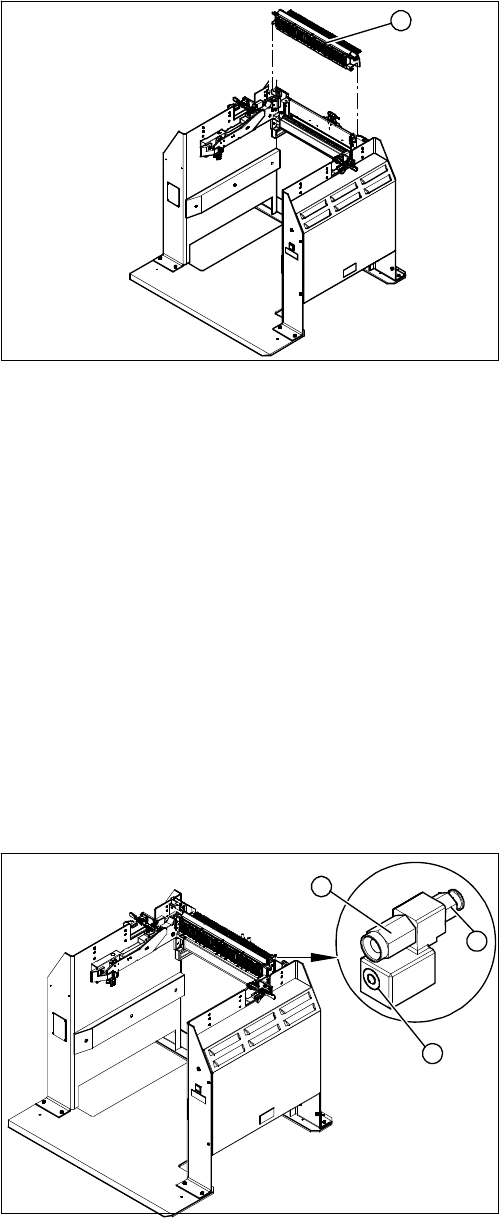
3.12.8 Replacing the Complete Coupling - Earthing and Compressed Air for the Bulk Case
Replacing the Complete Coupling - Earthing and Compressed Air for the Bulk Case
Parts, Equipment and Tools
You can either replace the individual coupling socket or the complete coupling unit for earthing and com-
pressed air.
▪ Coupling socket for compressed air coupling [03017026-xx]
▪ Coupling assembly for ground and compressed air [03017025-xx]
Overview
1. Feeder Control Unit
1
1. Coupling socket for component trolley compressed
air coupling (bulkcase feeder)
2. Pneumatic connection to pneumatic control valve 5.5
bar
3. Component trolley ground coupling (bulkcase feeder)
3
1
2