00194440-10_SM_X-Series_Customer_en.pdf - 第168页
Service Work Modular PCB Conveyor System 3.6.9 Replacing the Lifting T able St abilizer (Stabilizer Unit) [00358684-xx] 168 Service Manua l SIPLACE X Series 3.6.9 3 . 6 . 9 R e p la c in g t h e L if t in g T a b le S t …
Service Work
3.6.8 Replacing the Lifting Table Unit Modular PCB Conveyor System
Service Manual SIPLACE X Series 167
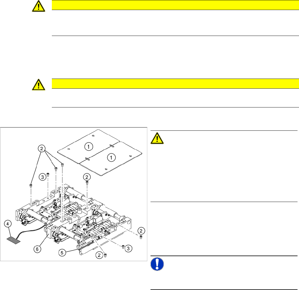
► Loosen the screws (2) and (3), fastening the lifting table unit.
► Remove the cover on the conveyor conversion board and unplug the connection cable (4) from the
lifting table unit.
► Unplug the compressed air connection (5).
► Carefully lift the lifting table (6) off the locating pins.
Installation
► Check the lifting table speed and the functionality of the PCB clamping device, without the lifting table
plate.
► If necessary, readjust the values. ("5.4.8 Lifting Table Functions" [ ➙ 339])
► Carefully place the lifting table plate (1) onto the lifting table unit and tighten the fastening screws
diagonally, so that the lifting table plate does not stick.
► Check the lifting table speed once the lifting table plate has been installed.
CAUTION
Screw positions!
Do not loosen the screws directly next to item (2)! If you do, the lifting table mechanics will be
displaced which could lead to tension and increased wear.
CAUTION
Heavy machine part!
When removing the lifting table, remember it is heavy (17.5 kg).
CAUTION!
Deaerate the lifting table valve!
When using a SIPLACE X4I or any PCB conveyors with
a bumper length of 35 mm, the lifting table valve inlet 2
must be de-aerated before reassembly. This ensures
free movement of the mechanism.
The lifting table mechanism can be raised during assem-
bly, to prevent distortion of the lifting table plate.
► Lift the lifting table unit (6) into the machine and posi-
tion it on the locating pins.
► Screw in the fastening screws (2) and (3).
► Reconnect to the electrical (4) and compressed air
(5) systems.
NOTICE!
Run the tables under the mechanics so that these are not
damaged when you move the lifting table upwards.
Service Work
Modular PCB Conveyor System 3.6.9 Replacing the Lifting Table Stabilizer (Stabilizer Unit) [00358684-xx]
168 Service Manual SIPLACE X Series
3.6.9
3.6.9 Replacing the Lifting Table Stabilizer (Stabilizer Unit) [00358684-xx]
Replacing the Lifting Table Stabilizer (Stabilizer Unit) [00358684-xx]
Overview
Tools and equipment required
▪ Torque wrench with plug-in ratchet [00386175-xx]
▪ Plug-in wrench 16 mm [00386177-xx]
Removal
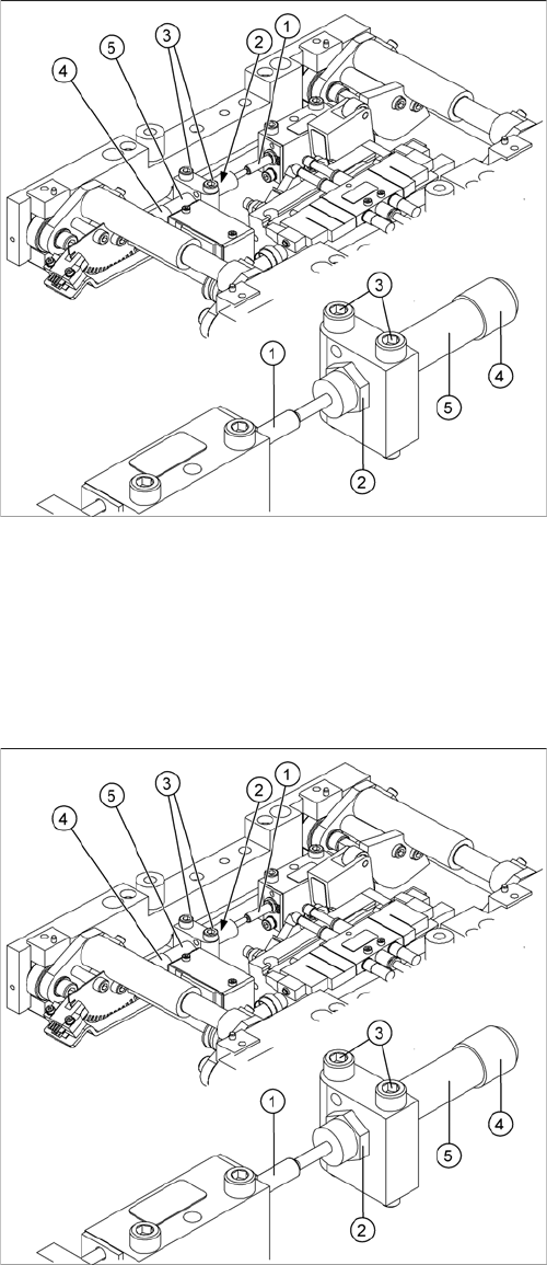
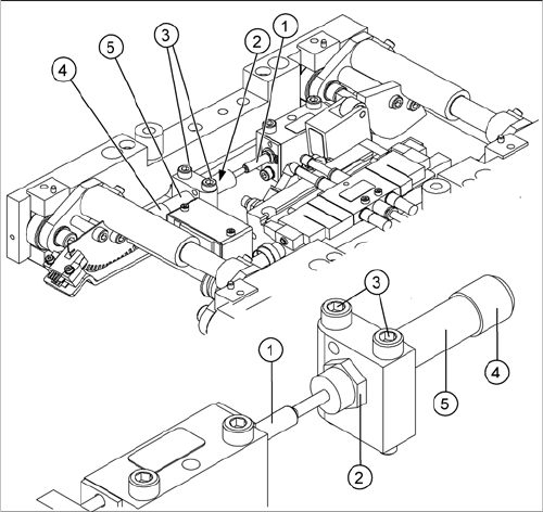
1. Actuator
2. Locknut
3. Fastening screws
4. Handle
5. Stabilizer [00358684-xx]
The stabilizer enables the lifting table to be moved gently
upwards. It prevents the PCBs from being clamped in
with too much impact.
The stabilizer consists of the shock absorber [00367737-
xx] and the damping block [00367782-xx].
► Move the PCB conveyor to the position which gives
you best access to the lifting table.
► Move the Y gantries into the area outside the PCB
conveyor.
► Switch off the machine and secure it to prevent unau-
thorized reactivation.
► Loosen the screws fastening the lifting table plate and
remove the lifting table plate from the lifting table unit.
► Loosen the two screws (3) holding the stabilizer (5).
► Undo the locknut (2) and take the stabilizer by its han-
dle (4), twisting it out of the mounting block.
Service Work
3.6.9 Replacing the Lifting Table Stabilizer (Stabilizer Unit) [00358684-xx] Modular PCB Conveyor System
Service Manual SIPLACE X Series 169
Installation and adjustment
► Insert and twist the new stabilizer (5) until the plunger
just touches the actuator (1), so that the lifting table
can be gently moved upwards.
► Using the torque wrench:
Secure this position with the locknut (2) tightened to
8Nm.
► Check whether the stabilizer has been fixed onto the
mounting block with the locknut and that the stabilizer
plunger has a gap of approx. 0.1 mm to the actuator
(gap in untriggered mode). In this default setting, the
lifting table should move up gently.
► If this is not the case, loosen the locknut and turn the
stabilizer approx. one rotation into the mounting
block.
► Fit the lifting table plate.
► Start SITEST and move the lifting table up.
► The lifting table should move up gently i.e. you should
not hear the PCB clamping device audibly locking
into place and no clamping device error messages
should be issued.
► Check the speed of the lifting table cylinder and cor-
rect where necessary.