00194440-10_SM_X-Series_Customer_en.pdf - 第368页
Description of the Circuit Boards Gantry 6.2.3 Head Interface C500 368 Service Manua l SIPLACE X Series 6.2.3.2 6 . 2 . 3 . 2 D I P S w it c h e s o n t h e H e a d I n t e r f a c e DIP Switches on the Head Interface * …
Description of the Circuit Boards
6.2.3 Head Interface C500 Gantry
Service Manual SIPLACE X Series 367
6.2.3.1
6.2.3.1 LEDs on the Head Interface
LEDs on the Head Interface
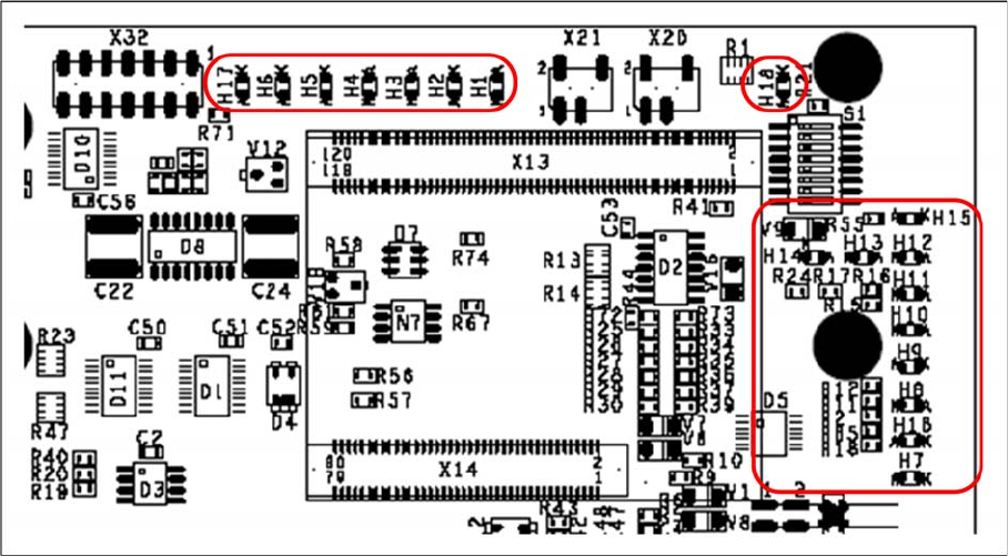
Head interface with status LEDs
LED H1-H6,H17,H18 (functional check)
▪ H17 SPI - Serial parallel interface (Test)
▪ H6 D-ON - digital ON 5V DC/DC converter (power supply head interface, generated from the 24V)
▪ H5 H-OK - Head adapter board connected
▪ H4 C-In - CAN Internal (status off)
▪ H3 MRST - Main Reset (always off)
▪ H2 F-UC – Failure - UC test
F-UC flashes red after machine is switched on:
- eSW was unable to execute one or more functions or to initialize a subsystem.
- flashes while the production power fail signal is active or 15V missing.
▪ H1 MP - Main Power fail, mean 5 V power supply being missing at the machine (e.g. CAN Bus)
▪ H18 1 Wire LED shows the high level on PIN 1 of 5V ON is green --> OK
LED H7- H15, H1B (LEDs for voltages)
▪ H14 Vcc - shows the output signal of the DC/DC converter (H6) +5 V
▪ H13 N15V – -15 V for TwinHead --> force measurement board (not for X4I)
▪ H15 P3.3V - Controller OK
▪ H12 P15V - Plus +15 Volt light barrier bottom C&P head
▪ H11 P24V - 24 V power supply (e.g.stepping motor)
▪ H10 AV ER - Failure 5 V
▪ H9 EN AN – 16 bit processor connected --> supply voltage OK
▪ H8 P5V - 5 V power supply track signals X axis --> red LED ON at error
▪ H1 B P5V – 5 V power supply for digital switching --> outside tolerance
▪ H7 X-Temp - Temperature monitoring X axis
Description of the Circuit Boards
Gantry 6.2.3 Head Interface C500
368 Service Manual SIPLACE X Series
6.2.3.2
6.2.3.2 DIP Switches on the Head Interface
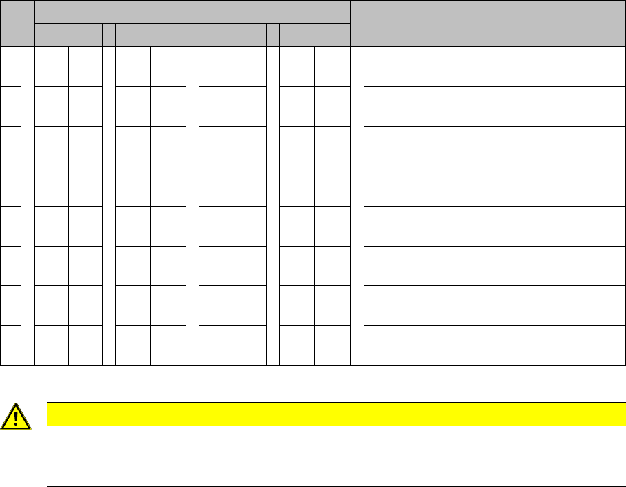
DIP Switches on the Head Interface
* Not all gantries may be available, depending on the machine type.
S Gantry* Comments
1 2 3 4
1OF
F
ON OF
F
ON P0 - Gantry address switch 1
2OF
F
OF
F
ON ON P1 - Gantry address switch 2
3ONONONONCAN R - CAN terminator (always OFF for
TwinHead)
4OF
F
OF
F
OF
F
OF
F
Boot - CAN processor 16 bit
5OF
F
OF
F
OF
F
OF
F
Reset - CAN processor 16 bit
6OF
F
OF
F
OF
F
OF
F
C0 - CAN Address switch
7OF
F
OF
F
OF
F
OF
F
C1 - CAN Address switch
8OF
F
OF
F
OF
F
OF
F
WPE - Write protect enable at the moment
OFF
CAUTION
Switch 3 (does not apply for X4I machines)
With Head Modularity pay attention: That terminating CAN resistor is set correctly:
Switch 3 is set to ON for C&P heads, to OFF for Twin heads.
Description of the Circuit Boards
6.2.4 DIP Switch on the Vision Board Gantry
Service Manual SIPLACE X Series 369
6.2.4
6.2.4 DIP Switch on the Vision Board
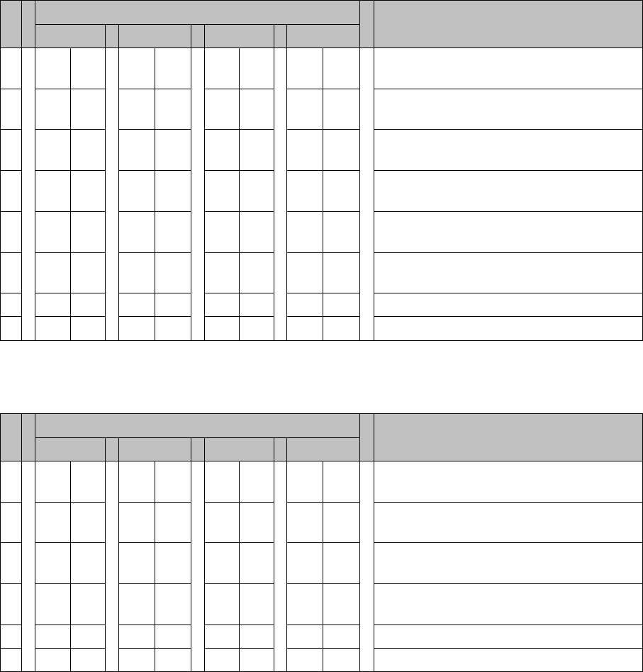
DIP Switch on the Vision Board
6.2.4.1
6.2.4.1 DIP Switch on the Vision Board (Digital Version 01)
DIP Switch on the Vision Board (Digital Version 01)
* Not all gantries may be available, depending on the machine type.
6.2.4.2
6.2.4.2 DIP Switch on the Vision Board (Digital Version 02)
DIP Switch on the Vision Board (Digital Version 02)
* Not all gantries may be available, depending on the machine type.
S Gantry* Comments
1 2 3 4
1OF
F
OF
F
OF
F
OF
F
Boot - CAN processor 16 bit on sub board
2OF
F
OF
F
OF
F
OF
F
Reset - CAN processor 16 bit on sub
board
3OF
F
ON OF
F
ON P0 - Gantry address switch 1
4OF
F
OF
F
ON ON P1 - Gantry address switch 2
5OF
F
OF
F
OF
F
OF
F
WPE - Write protect enable, currently OFF
6OF
F
OF
F
OF
F
OF
F
CAN R - Switch terminator CAN bus
7ONONONONTest 1 - CAN 1 MBit/s --> ON
8ONONONONTest 0 - CAN group --> ON
S Gantry* Comments
1 2 3 4
1OF
F
OF
F
OF
F
OF
F
Reset - CAN processor
2OF
F
ON OF
F
ON PID0 address switch 1 -> gantry
3OF
F
OF
F
ON ON PID1 address switch 2 -> gantry
4OF
F
OF
F
OF
F
OF
F
CAN R - switch for the terminal resistor on
the CAN bus
5ONONONONSpeed: ON = 1 Mbit/s, OFF = 500 Kbit/s
6ONONONONCAN ID - for X machine ON