00194440-10_SM_X-Series_Customer_en.pdf - 第375页
Description of the Circuit Boards 6.3.1 Conveyor Control TSP 301 Conveyor Service Manual SIPLACE X Series 375 6.3.1.5 6 . 3 . 1 . 5 S ie m e n s / S M E M A T S P 3 0 1 I n t e r f a c e D e s c r ip t io n Siemens/SMEMA…

Description of the Circuit Boards
Conveyor 6.3.1 Conveyor Control TSP 301
374 Service Manual SIPLACE X Series
H69 IN Option plug placement area 2: input 6
H70 Cod. Option plug, placement area 1: coding 1
H71 Cod. Option plug, placement area 1: coding 2
H72 Cod. Option plug, placement area 1: coding 3
H73 Cod. Option plug, placement area 2: coding 1
H74 Cod. Option plug, placement area 2: coding 2
H75 Cod. Option plug, placement area 2: coding 3
H76 Out Lifting table, placement area 1: valve up
H77 Out Lifting table, placement area 1: valve down
H78 Out Lifting table, placement area 2: valve up
H79 Out Lifting table, placement area 2: valve down
H80 Out Laser light barrier, placement area 1: transmitter
H81 Out Laser light barrier, placement area 2: transmitter
H82(ao) Out Width adjustment unit 1: valve
H83(ao) Out Width adjustment unit 2: valve
H84 Out Not used
H85 Out Not used
H86 Out Not used
H87 Out Not used
H88 Out Not used
H89 Out Not used
H90 Out Not used
H91 Out Not used
H92 Out Option plug, placement area 1: output 1
H93 Out Option plug, placement area 1: output 2
H94 Out Option plug, placement area 1: output 3
H95 Out Option plug, placement area 2: output 1
H96 Out Option plug, placement area 2: output 2
H97 Out Option plug, placement area 2: output 3
H98(ao) Out Barcode reader track 1: start signal
H99(ao) Out Barcode reader track 2: start signal
Anzeige /Display I / O LED assignment
Description of the Circuit Boards
6.3.1 Conveyor Control TSP 301 Conveyor
Service Manual SIPLACE X Series 375
6.3.1.5
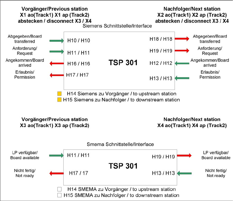
6.3.1.5 Siemens/SMEMA TSP 301 Interface Description
Siemens/SMEMA TSP 301 Interface Description
TSP 301 interface
Description of the Circuit Boards
Cutter 6.4.1 Control Unit on Cutter
376 Service Manual SIPLACE X Series
6.4
6.4 Cutter
Cutter
6.4.1
6.4.1 Control Unit on Cutter
Control Unit on Cutter
The jumper for the CAN bus addressing must be set according to the corresponding location in the ma-
chine.
See also
6.4.2 Control Unit on Cutter (CAN Nodes) [ ➙ 377]
NOTICE
Control unit [03006411-xx] is replaced by CAN node module.
This version of the control unit is replaced by the backwards compatible CAN node [03052027-
xx] module.
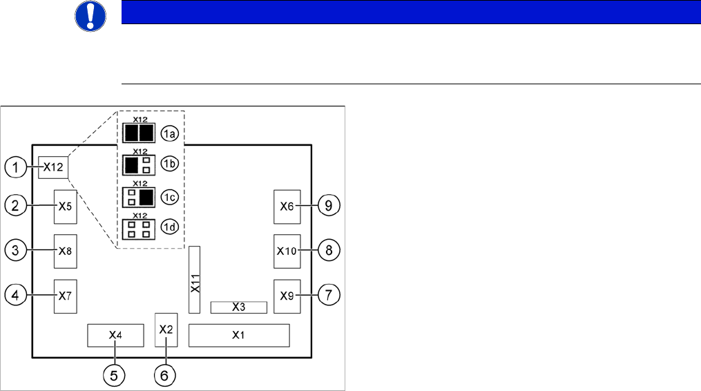
Jumper setting on the tape cutter unit (example of D4/D4i
shown)
1. X12 – Jumper for location encoding for cutter:
1a: gantry 1
1b: gantry 2
1c: gantry 3
1d: gantry 4
2. X5 – Voltage supply to valve (left)
3. X8 – Proximity switch for stroke cylinder out (left)
4. X7 – Proximity switch for stroke cylinder in (left)
5. X4 – CAN bus connection
6. X2 – Voltage supply for cutter +24 V and +5 V
7. X9 – Proximity switch for stroke cylinder in (left)
8. X10 – Proximity switch for stroke cylinder out (right)
9. X6 – Voltage supply to valve (right)