00194440-10_SM_X-Series_Customer_en.pdf - 第67页
Service Work 3.1.7 Replacing the Vision DC/DC Converter [03002280-xx] Electri cs and Control Service Manual SIPLACE X Series 67 3.1.7 3 . 1 . 7 R e p la c in g t h e V is io n D C / D C C o n v e r t e r [ 0 3 0 0 2 2 8 …
Service Work
Electrics and Control 3.1.6 Replacing the Computer Unit Assemblies
66 Service Manual SIPLACE X Series
3.1.6.2
3.1.6.2 Computer Unit with BoxPC
Computer Unit with BoxPC
See also
5.6.7 Installing the CAN Card Driver [ ➙ 358]
Computer unit with BoxPC [00351894-xx]
X series placement machines from machine number 600
onward and in X4I machines are equipped with box PCs
in the computer unit.
Depending on the machine type and the configuration up
to three box PCs are used.
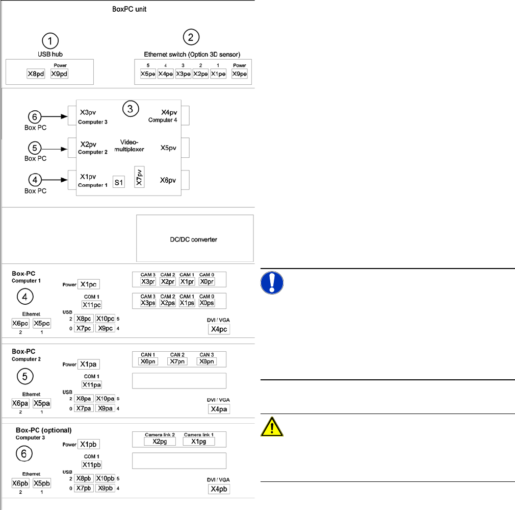
Position of assemblies in the computer unit
1. 4 port USB hub 2.0
2. Ethernet switch (only for optional 3D sensor)
3. Video multiplexer
4. Computer 1:
Station computer (up to SW 60x)
Vision computer (from SW 70x)
5. Computer 2:
Machine controller (MC) (up to SW 60x)
Station computer / MC (from SW 70x)
6. Computer 3:
Additional box PC - only for optional 3D sensor (not
for X4I)
NOTICE!
An external DVD drive is supplied with the delivery pack-
age.
From SW702 (X series from SW703) onwards, X4I ma-
chines are supplied with higher performance BoxPCs
[03072079-xx]. This means that machine control and the
Vision function are handled by only one BoxPC.
CAUTION!
When fitting the box PC, make sure that it is not pushed
right to the back. This would cover the fan and impair the
cooling system.
Service Work
3.1.7 Replacing the Vision DC/DC Converter [03002280-xx] Electrics and Control
Service Manual SIPLACE X Series 67
3.1.7
3.1.7 Replacing the Vision DC/DC Converter [03002280-xx]
Replacing the Vision DC/DC Converter [03002280-xx]
Parts, equipment and tools
▪ Circuit diagram folder for respective machine
► End all placement operations on the machine.
► Switch the machine off at the main switch.
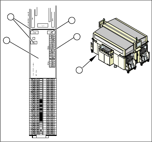
► Remove the cover on the main distributor (1) in sector
2.
► Mark the terminals on the Vision DC/DC converter (2)
and remove these from the terminal strip (3).
► Pull the terminals off the connectors (4).
► Swing the assembly (2) off the fixation bar.
► Plug in the new assembly.
► Plug in all connections/terminals.
31
30
29
28
27
1
2
3
4
5
6
7
8
9
10
11
12
13
14
15
16
17
18
19
20
21
22
23
24
25
26
X1ra
4
3
4
2
1
Service Work
Electrics and Control 3.1.8 Replacing the CAN Input/Output Module [00355051-xx]
68 Service Manual SIPLACE X Series
3.1.8
3.1.8 Replacing the CAN Input/Output Module [00355051-xx]
Replacing the CAN Input/Output Module [00355051-xx]
Overview
Removal/installation
► End all placement operations on the machine.
► Switch the machine off at the main switch.
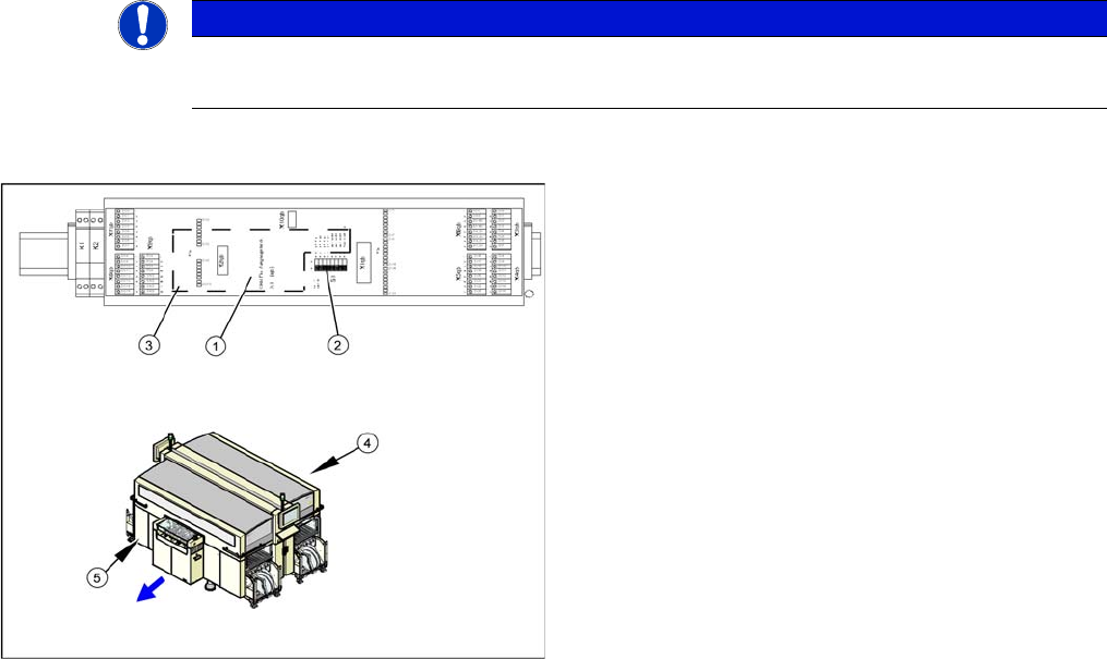
► Remove the cover on the main distributor (5) in sector 2 or on the subdistributor (4) in sector 4.
► Mark the terminals on the CAN input/output module and remove these from the terminal strips and
connectors.
► Remove the assembly (3) from the fixation bar.
► Fit the new assembly and plug in all connections.
► Check the DIP switch (2) on the assembly. The switch position must be set according to the replaced
assembly.
► Check the firmware and perform a download, if needed.
See also
5.6.2 Checking the Firmware Function [ ➙ 350]
NOTICE
A further CAN input/output module is situated on the subdistributor (sector 4).
► The replacement follows the same procedure.
1. Installation point for 1 wire RS232 bridge (plugged in)
2. DIP switch
3. CAN input/output module assembly
4. Subdistributor
5. Main Distributor