00194440-10_SM_X-Series_Customer_en.pdf - 第281页
Settings 5.2.3 C&P6/12 Axis Control Service Manual SIPLACE X Series 281 5.2.3.3 5 . 2 . 3 . 3 S t a r A x is C o n t r o l S y s t e m Star Axis Control System Checking the Star Axis Dynamics Star axis control system…
Settings
Axis Control 5.2.3 C&P6/12
280 Service Manual SIPLACE X Series
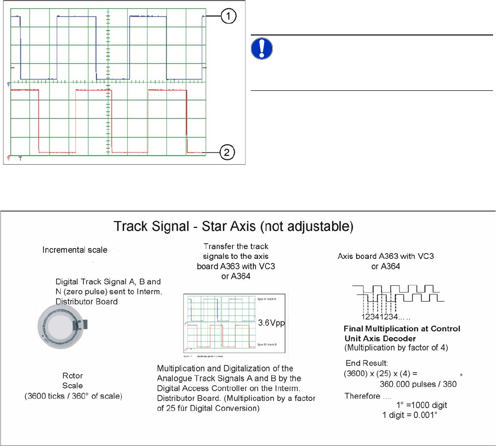
Preparing Track Signals for Star Axis Control (Example)
Digital head axis track signals
1. Track A
2. Track B
NOTICE!
The pulse width is dependent on the speed, the phase lo-
cation is dependent on the direction.
Settings
5.2.3 C&P6/12 Axis Control
Service Manual SIPLACE X Series 281
5.2.3.3
5.2.3.3 Star Axis Control System
Star Axis Control System
Checking the Star Axis Dynamics
Star axis control system
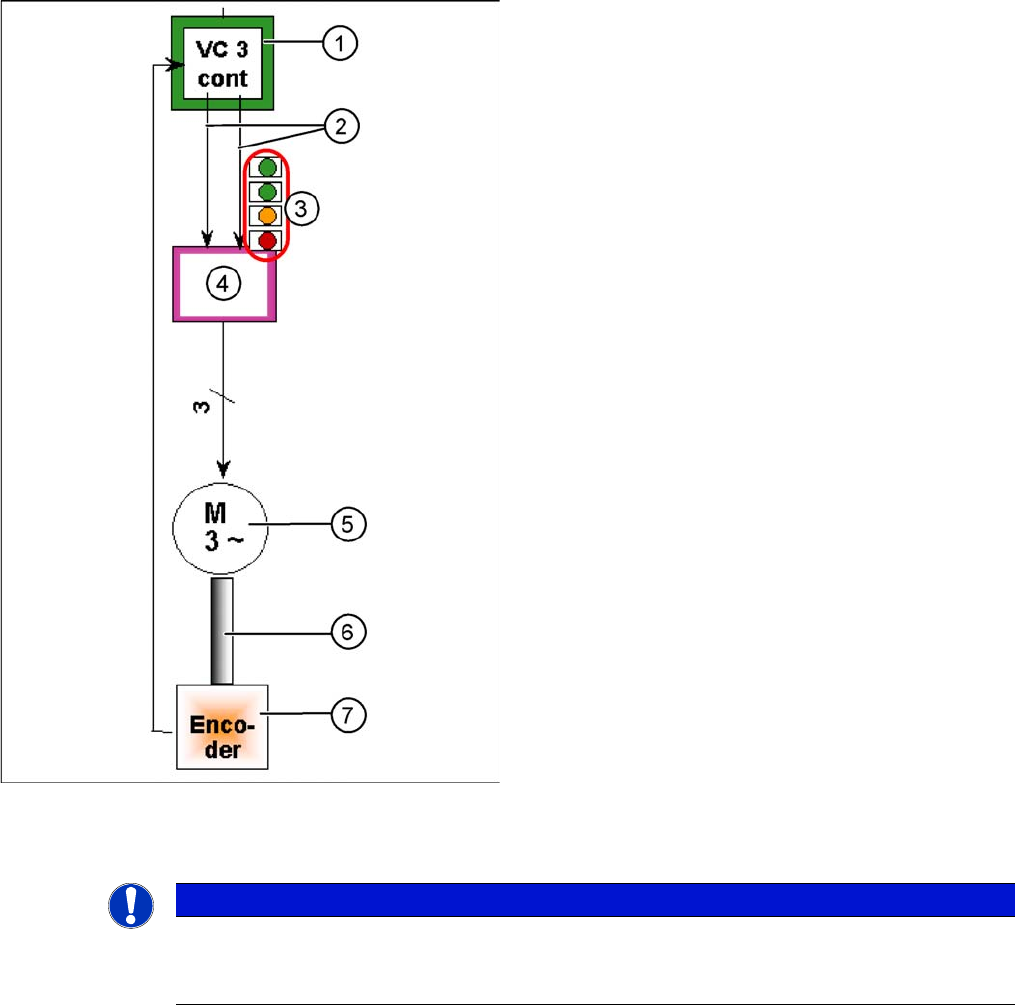
The star axis is driven via a 3-phase AC stepping motor
with an intermediate circuit voltage of 120 V. The activa-
tion is via two track signals (phase shift 120°) from the
VC3 controller Itarget "W" and I-target "U". The third
phase is calculated automatically.
1. Axis controller board A363 with VC3 controller (VC =
Velocity Commutation) or A 364
2. Control signals I target "W" and I target "U"
3. LEDs on servo amplifier:
4. Servo amplifier
5. 3 phase AC motor.
6. Between the motor and the incremental encoder
there is a fixed mechanical connection.
7. Incremental encoder: transmits the exact position of
the axis to the axis card. (The track signals are the
only feedback signals for the axes).
The servo board controls the motor directly.
NOTICE
Setting the axes
Before adjusting the axes, make sure that the machine has reached its operating temperature.
Switch the machine on at least 30 minutes before you begin work.
Settings
Axis Control 5.2.3 C&P6/12
282 Service Manual SIPLACE X Series
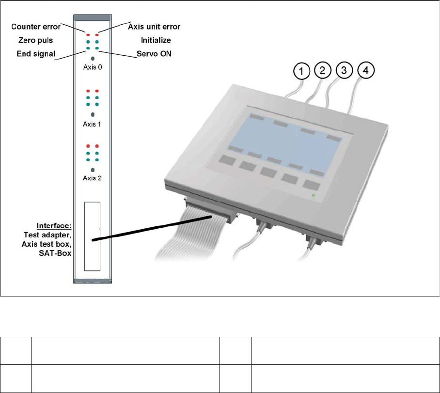
Measurement Setup with SAT Box and A363
Measurement setup with SAT box
Assignment of output leads by the SIPLACE Axis Tester and connection to the oscilloscope.
1 Vnom. output signal is currently not needed
for checking the HF dynamics.
3 Position deviation connected at CH1
2 Uncommutated current signal (Vreg), con-
nected to CH2
4 End position signal connected at CH3