00194440-10_SM_X-Series_Customer_en.pdf - 第121页
Service Work 3.3.12 Replacing the Head Adapto r on the Pick&Place Module [030 00902-xx] Gantries Service Manual SIPLACE X Series 121 3.3.12 3 . 3 . 1 2 R e p la c in g t h e H e a d A d a p t o r o n t h e P ic k &am…
Service Work
Gantries 3.3.9 Fitting and Removing the Y Axis Bumper
120 Service Manual SIPLACE X Series
3.3.9
3.3.9 Fitting and Removing the Y Axis Bumper
Fitting and Removing the Y Axis Bumper
3.3.10
3.3.10 Replacing the X Scale
Replacing the X Scale
3.3.11
3.3.11 Replacing the Y Scale
Replacing the Y Scale
CAUTION
Y axis bumper
The Y axis bumpers may only be removed or replaced by the SIPLACE Service team.
NOTICE
Service Work Conveyor
This service task may only be performed by specially trained SIPLACE service technicians. The
procedure is described in a separate manual.
NOTICE
Service Work Conveyor
This service task may only be performed by specially trained SIPLACE service technicians. The
procedure is described in a separate manual.
Service Work
3.3.12 Replacing the Head Adaptor on the Pick&Place Module [03000902-xx] Gantries
Service Manual SIPLACE X Series 121
3.3.12
3.3.12 Replacing the Head Adaptor on the Pick&Place Module [03000902-xx]
Replacing the Head Adaptor on the Pick&Place Module [03000902-xx]
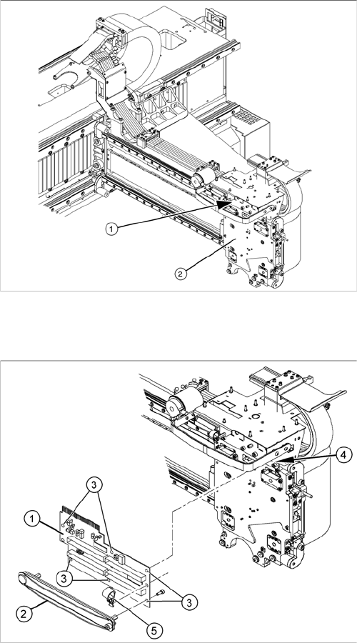
Overview
Removal/installation
1. Head adapter P&P
2. Head plate
1. Head adapter
2. Cable clamps (consisting of upper and lower part)
3. Fastening screws
4. Spacers
5. Hose fixture
► Remove the upper part of the cable clamp (2).
► Unplug both flat ribbon cables to the P&P modules
from the head adapter (1).
► Undo the 6 fastening screws (3).
► Loosen the hose mount (5) and the spacers, (4)
where necessary.
► Carefully pull the head adapter (1) down and out and
dismantle the lower part of the cable clamp, if neces-
sary.
► Fit the new head adapter with the lower part of the ca-
ble clamp and reconnect to the electrical system.
► Fit the cable clamp assembly and attach the hose
mount.
► Make sure that the cables are seated firmly during
axis movement and that no sections of them will be
subject to wear or damage.
Service Work
Placement heads 3.4.1 Fast Head Exchange
122 Service Manual SIPLACE X Series
3.4
3.4 Placement heads
Placement heads
3.4.1
3.4.1 Fast Head Exchange
Fast Head Exchange
By means of the Fast Head Exchange (FHE) it is possible to replace a placement head within 15 min-
utes.
See also
3.4.2 Replacing the CPP Head [ ➙ 127]
3.4.1.1
3.4.1.1 Requirements
Requirements
If the following requirements are met, the heads can be replaced using the FHE and are ready for use
after a brief calibration.
▪ Software 702:
The software version 702 only supports replacement of placement heads which have the same type,
i.e., replacing a C&P20A with another C&P20A head or a CPP with another CPP head.
– SW 702 and the current eSW versions
– The placement heads in the machine have the calibration data stored in the EEPROM.
– The "segment offset bottom" for the second head height has been determined by a double meas-
urement of the data.
– A fast head exchange is not possible for a CPP head with a stationary camera.
– A fast head exchange is not possible for the TwinHead.
– The head plate is equipped with a hook and the placement head with the corresponding eyelet.
– Torx screws are used as head screws.
– The screws are undetachably fixed to the head.
– The heads to be fitted must already be equipped with calibration nozzles.
▪ Software 703:
With SW 703 the fast head exchange has been enhanced by the following functions:
– Head and component camera can now be separated on CPP and C&P20A heads.
– A verification is carried out on all SX machines.
– The "segment offset bottom" for the second head height is calculated by interpolation.
– You can use precalibrated heads from the head test rig or the stock.
– C&P20A heads are equipped with a T-piece between the pressure control valve and the return
unit, in order to reduce the number of compressed air connections at the pneumatic distributor.