00194440-10_SM_X-Series_Customer_en.pdf - 第63页
Service Work 3.1.5 Replacing the Axis Uni t Assemblies [00353054-xx] Electrics and Control Service Manual SIPLACE X Series 63 3.1.5.1 3 . 1 . 5 . 1 O v e r v ie w o f A x is U n it ( w it h A 3 6 3 ) [ 0 0 3 5 3 0 5 4 - …
Service Work
Electrics and Control 3.1.5 Replacing the Axis Unit Assemblies [00353054-xx]
62 Service Manual SIPLACE X Series
3.1.5
3.1.5 Replacing the Axis Unit Assemblies [00353054-xx]
Replacing the Axis Unit Assemblies [00353054-xx]
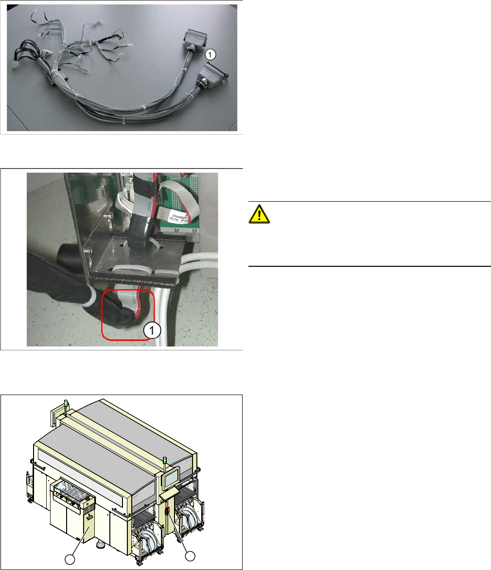
Adapter cable harness
► Connect the Harting connector (1) of the adapter ca-
ble harness to the relevant connection point on the
machine.
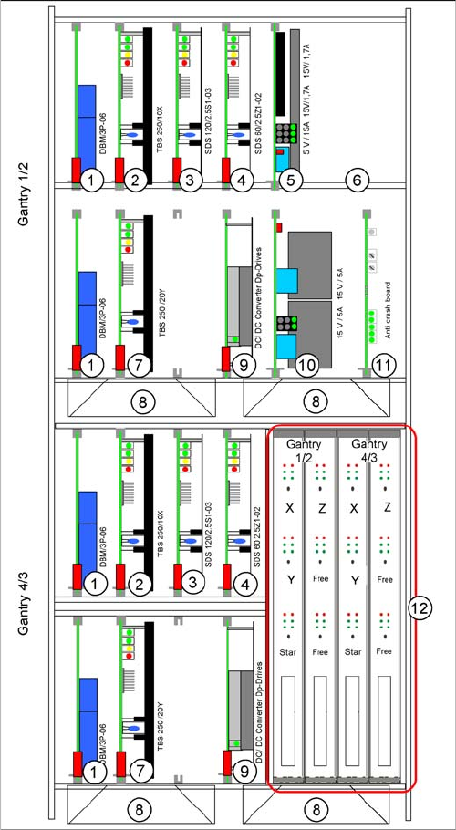
► Hook the axis unit back into the guide rail in the ma-
chine. Carefully stow the cables in the machine.
CAUTION!
Make sure you do not damage any cables. Pay particular
attention to the lower part of the flat ribbon cable harness
(1). Make sure this does not rub against any parts.
► Push the axis unit into the machine and fit the protec-
tive cover.
► Switch the machine back on and perform a function
test.
► End all placement operations on the machine.
► Switch the placement system off at the main switch
(1).
► Remove the cover on the axis unit (2).
1
2
Service Work
3.1.5 Replacing the Axis Unit Assemblies [00353054-xx] Electrics and Control
Service Manual SIPLACE X Series 63
3.1.5.1
3.1.5.1 Overview of Axis Unit (with A363) [00353054-xx]
Overview of Axis Unit (with A363) [00353054-xx]
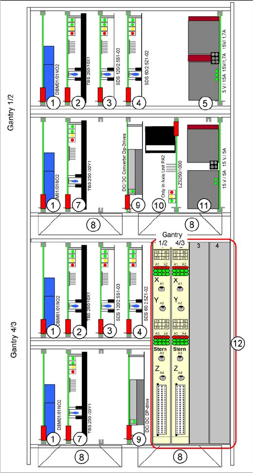
Axis unit with A363: configuration example C&P20 and
C&P20
The axis card A363 was fitted up to machine number B-
336.
The plug-in cards vary according to the machine configu-
ration. This example shows an axis unit with two C&P20
heads in placement area 1.
1. Brake board for each X axis and Y axis
2. Servo amplifier X axes
3. Star axis servo amplifier
4. Servo amplifier Z axis
5. Power supply +/- 15, +5 V
6. Ballast circuit (only in axis unit PA2)
7. Servo amplifier Y axes
8. Fan unit
9. DC/DC converter, DP drives
10. Power supply +/- 15V
11. Anti-crash board
12. Axis controller boards
Service Work
Electrics and Control 3.1.5 Replacing the Axis Unit Assemblies [00353054-xx]
64 Service Manual SIPLACE X Series
3.1.5.2
3.1.5.2 Overview of Axis Unit (with A364)
Overview of Axis Unit (with A364)
Axis unit with A364: configuration example C&P20 +
C&P20
From X-Series machine number B-337 and X4I onwards,
the axis card A364 [03041865-xx] has been fitted.
The anticrash board is no longer used as its function is in-
tegrated into the A364.
The plug-in cards can vary, according to the machine
configuration. This example shows an axis unit with two
C&P20 heads in placement area 2.
1. Brake board for each X axis and Y axis
2. Servo amplifier X axes
3. Star axis servo amplifier
4. Servo amplifier Z axis
5. Power supply +/- 15, +5 V
6. -
7. Servo amplifier Y axes
8. Fan unit
9. DC/DC converter, DP drives
10. Ballast circuit (only in axis unit PA2)
11. Power supply +/- 15V
12. Axis controller boards