00194440-10_SM_X-Series_Customer_en.pdf - 第166页
Service Work Modular PCB Conveyor System 3.6.8 Replacing the Lifting Table Unit 166 Service Manua l SIPLACE X Series 3.6.8 3 . 6 . 8 R e p la c in g t h e L if t in g T a b le U n it Replacing the Lifting Table Unit Part…
Service Work
3.6.7 Replacing the Conveyor Toothed Belt (2.5 mm Width) Modular PCB Conveyor System
Service Manual SIPLACE X Series 165
Installation
CAUTION
Check the toothed belt before fitting it.
► Hold the toothed belt between two fingers and let it hang down. The toothed belt should be
roughly O shaped and when hanging freely may not turn by more than 90°!
CAUTION
Do not damage the toothed belt!
The toothed belts must not be stretched or bent!
The minimum radius of the toothed belt is 16 mm.
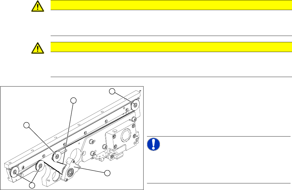
► Feed the new conveyor toothed belt (2) into the drive
unit and weave it round the deflection pulleys (3).
► Insert the tape drive (mount) or drive unit (1) with the
conveyor toothed belt (2) and fasten. In the case of
a drive unit, you will need to restore the cable connec-
tions.
NOTICE!
When replacing the belt on the passive side (tape drive
without drive unit), set the track width to 50 mm. The tape
drive must be aligned towards the active side, allowing
smooth axial movement of the hexagonal shafts.
► Tighten the fastening screws.
► Adjust the belt tension.
► Once you have loosened the drive unit cables, check
their direction of rotation.
3
3
1
3
2
Service Work
Modular PCB Conveyor System 3.6.8 Replacing the Lifting Table Unit
166 Service Manual SIPLACE X Series
3.6.8
3.6.8 Replacing the Lifting Table Unit
Replacing the Lifting Table Unit
Parts
▪ Lifting table unit for single conveyor [03029170-xx],
backwards compatible to [00358653-xx]
▪ Lifting table unit for dual conveyor [03029171-xx],
backwards compatible to [00358654-xx]
▪ Lifting table unit for dual conveyor of X4I and quad lane [03059051-xx]
▪ Lifting table unit for single conveyor of X4I [03065192-xx]
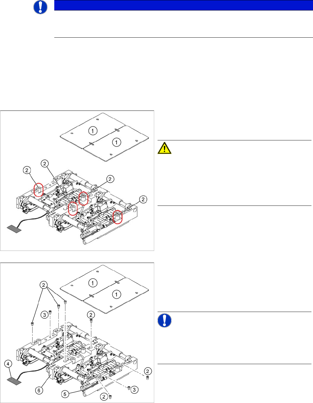
► Loosen the screws fastening the lifting table plate (1) diagonally and evenly and then remove the
lifting table plate from the lifting table unit.
NOTICE
Single, dual and quad lane conveyor
The replacement is shown here using the example of the lifting table unit for the dual or quad
lane conveyor (QC). Replacement of the lifting table unit for the single conveyor is the same.
New lifting table bumper for SIPLACE X4I
The bumpers (2) under the lifting table plate (1) are now
35 mm long.
CAUTION!
Loosen the lifting table plate screws diagonally and even-
ly!
The screws fixing the lifting table plate of the SIPLACE
X4I and any future lifting tables with a bumper length of
35 mm must be loosened evenly, otherwise the lifting ta-
ble plate will be subjected to excessive tension.
1. Lifting table plates (dual conveyor shown here)
2. Six fastening screws for lifting table (M8x100)
3. Two fastening screws for lifting table (M6x50)
► Move the PCB conveyor to a suitable position from
which you have best access to the lifting table unit.
NOTICE!
Quad lane conveyor
When using a quad lane conveyor, it is advisable to move
the first conveyor edge to one side and the second to fifth
edges as far as possible to the other side.
Service Work
3.6.8 Replacing the Lifting Table Unit Modular PCB Conveyor System
Service Manual SIPLACE X Series 167
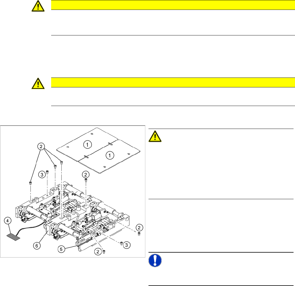
► Loosen the screws (2) and (3), fastening the lifting table unit.
► Remove the cover on the conveyor conversion board and unplug the connection cable (4) from the
lifting table unit.
► Unplug the compressed air connection (5).
► Carefully lift the lifting table (6) off the locating pins.
Installation
► Check the lifting table speed and the functionality of the PCB clamping device, without the lifting table
plate.
► If necessary, readjust the values. ("5.4.8 Lifting Table Functions" [ ➙ 339])
► Carefully place the lifting table plate (1) onto the lifting table unit and tighten the fastening screws
diagonally, so that the lifting table plate does not stick.
► Check the lifting table speed once the lifting table plate has been installed.
CAUTION
Screw positions!
Do not loosen the screws directly next to item (2)! If you do, the lifting table mechanics will be
displaced which could lead to tension and increased wear.
CAUTION
Heavy machine part!
When removing the lifting table, remember it is heavy (17.5 kg).
CAUTION!
Deaerate the lifting table valve!
When using a SIPLACE X4I or any PCB conveyors with
a bumper length of 35 mm, the lifting table valve inlet 2
must be de-aerated before reassembly. This ensures
free movement of the mechanism.
The lifting table mechanism can be raised during assem-
bly, to prevent distortion of the lifting table plate.
► Lift the lifting table unit (6) into the machine and posi-
tion it on the locating pins.
► Screw in the fastening screws (2) and (3).
► Reconnect to the electrical (4) and compressed air
(5) systems.
NOTICE!
Run the tables under the mechanics so that these are not
damaged when you move the lifting table upwards.