00194440-10_SM_X-Series_Customer_en.pdf - 第103页
Service Work 3.3.8 Replacing the Trailing Cable Gantries Service Manual SIPLACE X Series 103 Installation CAUTION Handling Handle the new trailing cable wit h care and enlist the help of a second person. Make sure that t…
Service Work
Gantries 3.3.8 Replacing the Trailing Cable
102 Service Manual SIPLACE X Series
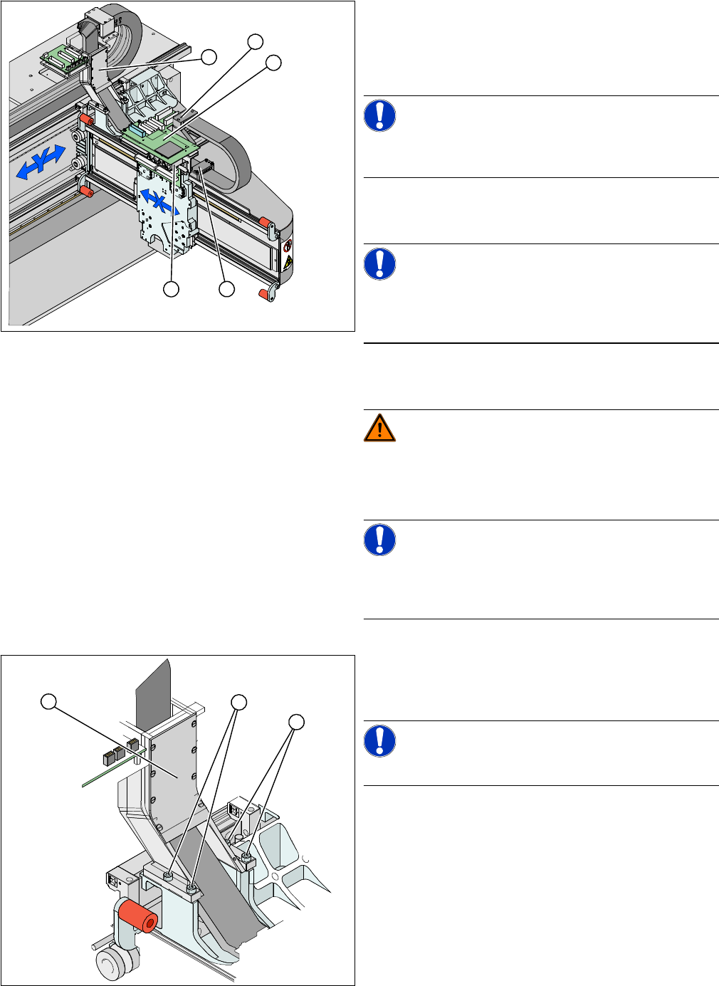
► Loosen the flat ribbon cable at the head board (1).
► Remove the pressure plate (3).
► Loosen the screws fastening the pressure plate (3) to
the head mount and the two screws at the gantry (5).
NOTICE!
Only loosen the fastening screws. The clamps for the flat
ribbon cable remain in place.
► Remove the head plate (1). The pneumatic distribu-
tors (2) located below are now accessible.
NOTICE!
Mark the installation position of the contact disks and
spacer bolts and take care not to lose them. These will
need to be correctly replaced later.
► Disconnect the hoses from the pneumatic distributor
(2).
WARNING!
Risk of injury to hands
Use the hose unlocking tool to remove the hoses
[03047090-xx].
NOTICE!
Cut the hoses with a suitable pairs of hose cutters and
dismantle the pneumatic distributor. The hoses can be
loosened more easily once they have been removed.
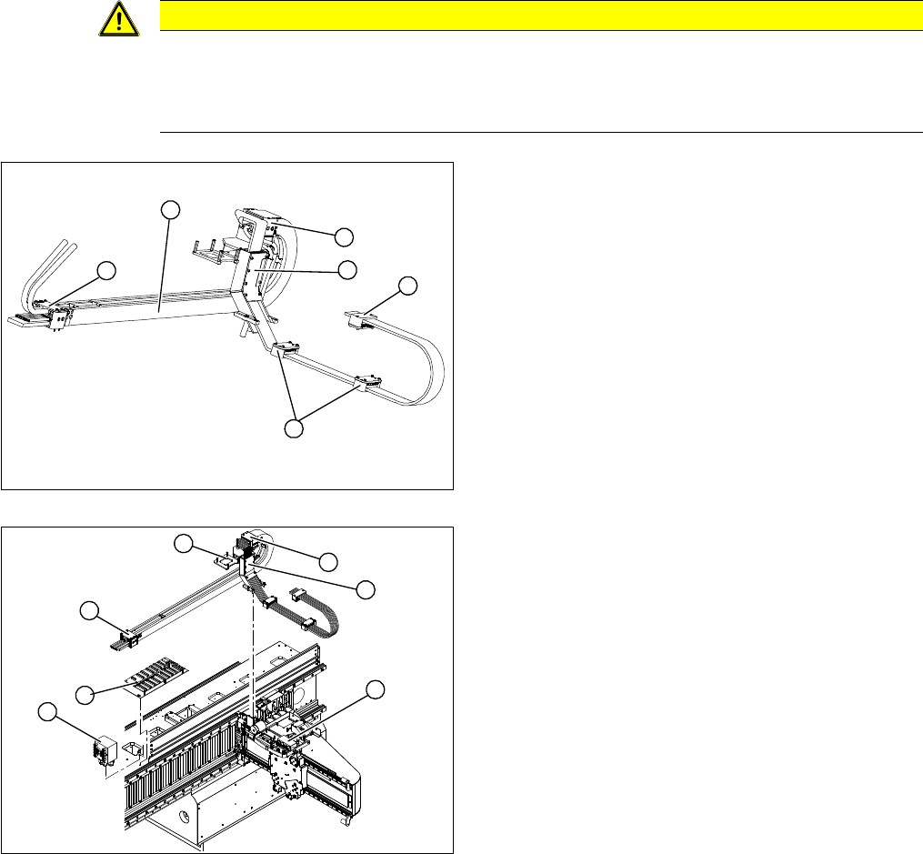
► Undo the four screws (1) fastening the trailing cable
console (2) and carefully remove the complete trailing
cable from the machine.
NOTICE!
The fastening screws have been secured with Loctite.
► If you have removed the pneumatic distributor, loos-
en the hoses now.
5
5
1
4
3
2
1
1
2
Service Work
3.3.8 Replacing the Trailing Cable Gantries
Service Manual SIPLACE X Series 103
Installation
CAUTION
Handling
Handle the new trailing cable with care and enlist the help of a second person. Make sure that
the flat ribbon cable and the pneumatic hoses are not rubbed against any parts or folded. Look
out for sharp edges.
1. Complete trailing cable unit
2. Pressure plates on the power track chain.
3. Pressure plates on the gantry
4. Pressure plates on the head mount
5. Trailing cable console
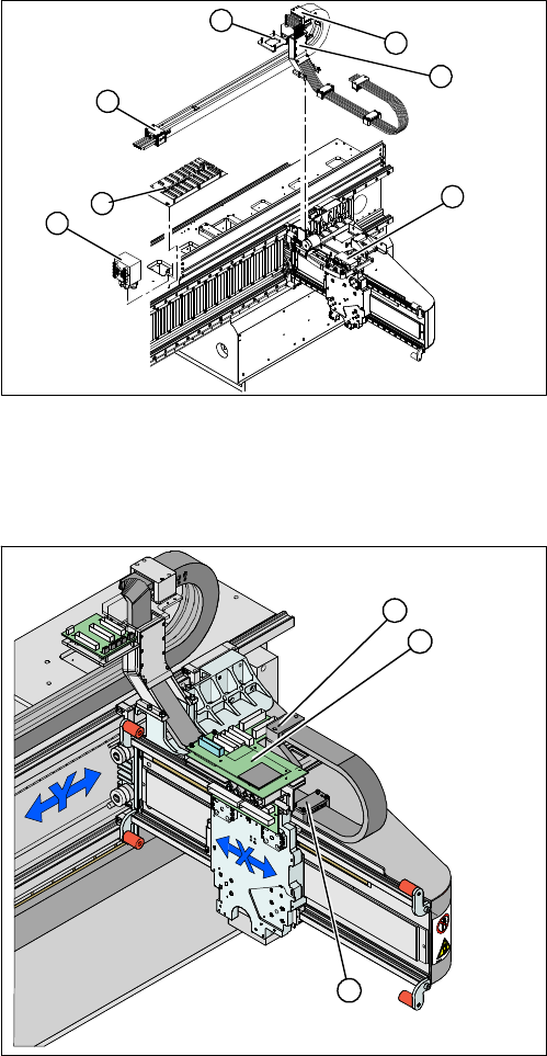
► Carefully insert the new trailing cable (1) into the pre-
scribed position. Make sure you do not twist it.
► Temporarily fasten the ends to the machine base
(e.g. by tying them).
► Fit the gantry interface board onto the cable clamp (4)
of the new trailing cable.
► Loosely fasten the trailing cable console (1) with a
screw.
► Clean the trailing cable contact surface on the ma-
chine base with a dry cloth.
► Starting from the trailing cable console (1), run the flat
ribbon cable and hoses to the appropriate connec-
tions:
⇨ Pneumatic distributor (2)
⇨ Trailing unit interface gantry (3)
⇨ Gantry interface (4)
⇨ Gantry distributor (5)
► Reconnect to the electricity supply. Observe the cor-
rect connector assignment.
2
5
1
4
3
2
2
5
4
6
6
1
3
Service Work
Gantries 3.3.8 Replacing the Trailing Cable
104 Service Manual SIPLACE X Series
► Shorten the pneumatic hoses to the optimum length.
Make sure that they are not too long or too short.
They must engage firmly but should not buckle.
► Reconnect to the compressed air supply. Observe
the correct connector assignment.
► Loosely fasten the pressure plates (6) to the machine
base.
► Check that the power track chain can run along the
top of the machine base without obstruction. Move
the Y axis back and forth to check this.
► If necessary, correct at the trailing cable console (1)
and at the pressure plates.
► Fix the two pressure plates (6) and the trailing cable
console (1). Use Loctite 241 locking varnish to secure
them.
► Tighten the fastening screws for the trailing cable
console (1) crosswise.
► Reconnect the cooling tubes to the Y motor.
► Fit the 3 pressure plates (1) at the gantry and head
mount (2).
► You will need to replace the cable supports for
SIPLACE HF machines up to MA219. See also
"3.3.8.5.4 Conversion for SIPLACE HF up to A 219"
[ ➙ 105].
► Fit the head board (3). Make sure you do not lose the
contact disks or spacer bolts.
► Plug in all connections/terminals. Observe the cor-
rect connector assignment.
► Fasten new cable ties at the original points.
► Replace all dismantled cover plates in their original
positions.
2
5
4
6
6
1
3
5
1
3
2