00194440-10_SM_X-Series_Customer_en.pdf - 第128页
Service Work Placement heads 3.4.2 Replacing the CPP Head 128 Service Manua l SIPLACE X Series Removal ► Switch off the machine, disconnec t it from the po wer supply and secure it to prev ent unauth orized reactivation.…
Service Work
3.4.2 Replacing the CPP Head Placement heads
Service Manual SIPLACE X Series 127
3.4.2
3.4.2 Replacing the CPP Head
Replacing the CPP Head
Parts, equipment and tools
▪ CPP placement head with camera SST29 [03070108-xx] or
CPP placement head without camera [03053528-xx]
▪ Torque screwdriver 100-500 Ncm [03078400-xx]
▪ Extension/straight TX20 [03073256-xx]
▪ Bit holder for Torque Vario-S screwdriver [03078706-xx]
▪ Component sensor protective cap [03080984-xx]
▪ Torx Allen screwdriver TX8 [03080081-xx]
▪ Calibration tool version 3 [03010565-xx]
▪ Calibration tool version SST23 [03034148-xx]
▪ For additional work to the placement head:
Service manual "C&P head" [DE: 00197462-xx]. [EN: 00197463-xx]
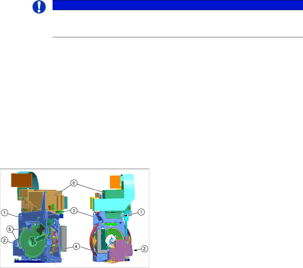
Overview
NOTICE
Fast Head Exchange (FHE)
► Observe the instructions in section "3.4.1 Fast Head Exchange" [➙122] when exchanging
a head.
1 to 4: Fixture holes (two each, depends on installation
height).
5: Dowel holes for the index pins
6: Component camera
Service Work
Placement heads 3.4.2 Replacing the CPP Head
128 Service Manual SIPLACE X Series
Removal
► Switch off the machine, disconnect it from the power supply and secure it to prevent unauthorized
reactivation. Observe the instructions in section "1.2 Preparatory Work..." [ ➙ 15].
► Loosen all four screws fastening the head with a long Torx screwdriver.
CAUTION
Take great care when dismantling the placement head!
The component sensor prisms, underneath the placement head, could be damaged.
► Never place the CPP head down on the component sensor.
► Fit the protective cap onto the component sensor for
the placement head.
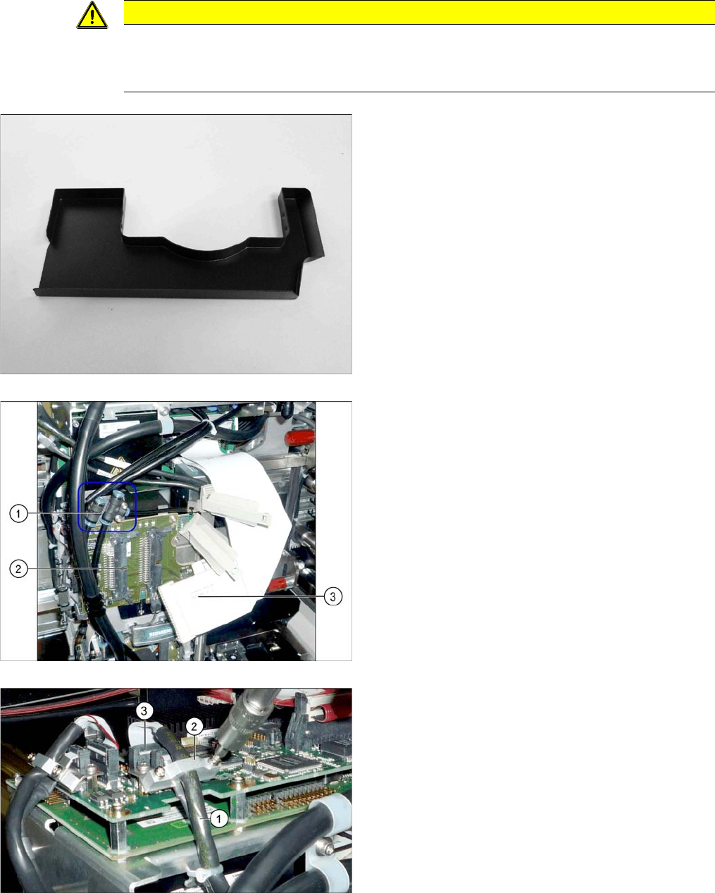
► Unplug the compressed air connections (1) from the
placement head. You may want to mark the positions,
to make clear assignment easier later on.
► Disconnect the flat ribbon cables (3) from the inter-
mediate distributor (2). You may want to mark the po-
sitions, to make clear assignment easier later on.
► Loosen the screws fastening the strain relief (2) on
the component camera cable (1) and carefully unplug
the cable. While unplugging the cable, press the
clamps on both sides of the connector (3). You may
want to mark the positions, to make clear assignment
easier later on.
Service Work
3.4.2 Replacing the CPP Head Placement heads
Service Manual SIPLACE X Series 129
► Carefully lift the head out of the locating pins on the head plate/from the hook.
Installation
► Follow the removal instructions in reverse order for installation. Also observe the following instruc-
tions:
See also
3.4.2.1 Preparing the Head for the Installation Height [ ➙ 130]
NOTICE
Additional work
► If you need to perform further work on this head (e.g. replacing spare parts), fit the head to
the head mount [03056231-xx].
CAUTION
Installation instructions
► Observe the correct installation height of the head! Read the service manual for your place-
ment head for more information.
► If you replace the head without the component camera, you will need to fit the old camera
onto the new head. Read the service manual for your placement head for more information.
► Make sure that the assembly position on the head plate is correct.
► Tighten the four fastening screws with a torque of 270 Ncm.
► Make sure that the flat ribbon cable is run correctly to the head adapter (see below).
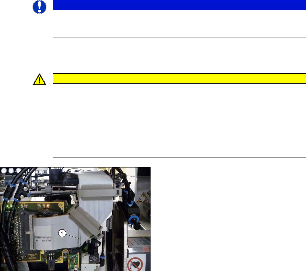
Correct running of flat ribbon cable to head adapter
► Make sure that the flat ribbon cable is run correctly to
the head adapter. In particular, the cables must lie in-
side one another at the 90 degrees turn (1) and not
on top of one another, otherwise the connections on
the head adapter could be easily confused.