00194440-10_SM_X-Series_Customer_en.pdf - 第266页
Settings Gantry Settings 5.1.7 Track Signals and Zero Pulse 266 Service Manua l SIPLACE X Series 5.1.7 5 . 1 . 7 T r a c k S ig n a ls a n d Z e r o P u ls e Track Signals and Zero Pulse 5.1.7.1 5 . 1 . 7 . 1 C h e c k i…
Settings
5.1.6 Mechanical Adjustment of the Incremental Encoder Gantry Settings
Service Manual SIPLACE X Series 265
5.1.5.4
5.1.5.4 Checking the Function of the Anticrash Board
Checking the Function of the Anticrash Board
Preparation
► Perform a complete reference run.
Testing the Proximity Switch on the Gantry
► Press the EMERGENCY STOP button.
► Unplug the relevant connector from the proximity switch.
► Release the EMERGENCY STOP button.
► Press the START button.
► Select the corresponding X or Y axis for the disconnected proximity switch.
SITEST:
► Select "Gantry" ==> "Choose gantry" ==> "Axis functions" ==> "Choose axis"
==> "Dynamic axis behavior" ==> "Set the travel path 9
(200.000 digits)".
▪ The anticrash board will trigger.
▪ The selected axis will brake in the relevant direction.
▪ As the anticrash board has triggered, you will see the following error message here:
"Gantry distance insufficient. Protective circuit reacted".
► Press the EMERGENCY STOP button.
► Reconnect the relevant proximity switch.
► Press the RESET button on the anticrash board.
► Release the EMERGENCY STOP button.
► Select "Cancel" and press the START button.
► The axis is now back in its normal state.
5.1.6
5.1.6 Mechanical Adjustment of the Incremental Encoder
Mechanical Adjustment of the Incremental Encoder
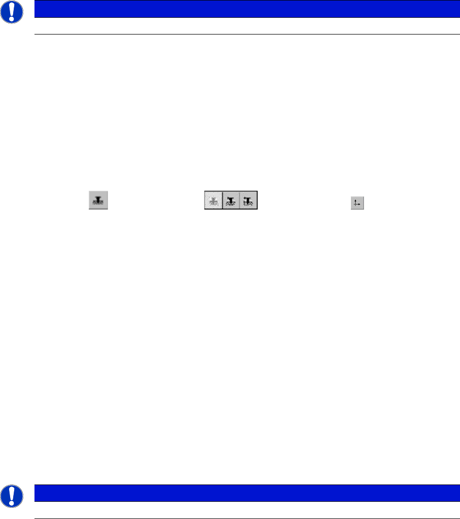
The incremental encoders (read units) on the X and Y axis are adjusted exactly to the position of the
incremental scale. The two limit marks on the incremental encoder show where the top/bottom positions
of the scale should be. The encoder is also mechanically set to a distance of 0.4 mm +/- 0.1 mm to the
incremental scale.
After this adjustment of the incremental encoder you have to check the zero pulse and track signals.
Correct installation should ensure correct count and zero pulse signals. For troubleshooting purposes
(error analysis and fixing), you will need to measures these signals with the oscilloscope. (See service
manual.)
See also
5.1.7 Track Signals and Zero Pulse [ ➙ 266]
NOTICE
The test is identical for all gantry groups.
NOTICE
To set this distance, use one or more small plastic disks with a total thickness of 0.4 mm.
Settings
Gantry Settings 5.1.7 Track Signals and Zero Pulse
266 Service Manual SIPLACE X Series
5.1.7
5.1.7 Track Signals and Zero Pulse
Track Signals and Zero Pulse
5.1.7.1
5.1.7.1 Checking the Zero Pulse Signal
Checking the Zero Pulse Signal
The zero pulse must be reliably and clearly recognized by the read head. To ensure this, you can check
both the analog and the digital zero pulse. Electronically controlled settings can not be performed on the
incremental length measurement system.
Measuring the Analog Zero Pulse Signal
Measurement procedure for checking the analog zero pulse and the analog track signals
NOTICE
New incremental encoder
Since 2007, machines have been equipped with a new incremental encoder (as in SIPLACE
D4). A larger measuring window allows you to compensate contaminants on the incremental
scale (up to approx. 3.5 mm).
Settings
5.1.7 Track Signals and Zero Pulse Gantry Settings
Service Manual SIPLACE X Series 267
Measurement Procedure
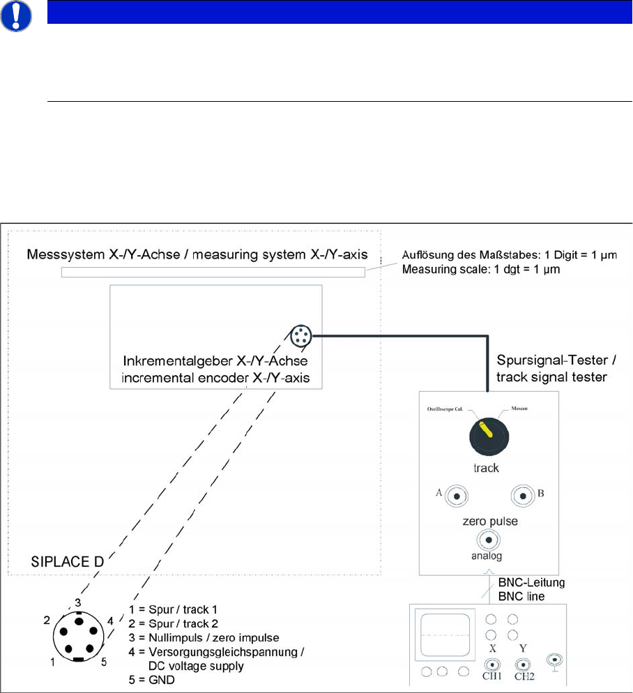
► Manually move the gantry over the first zero pulse.
► The following picture should appear on the oscilloscope.
Measuring the initial zero pulse position
► Connect the measurement tester to the incremental
encoder.
► Main power switch ON
► Connect the oscilloscope to the measurement tester.
► Set the measuring adapter to Calibrate the oscillo-
scope and position the signal at the top center of the
screen.
NOTICE
Zero pulse check
Check the first zero pulse after the limit switch.
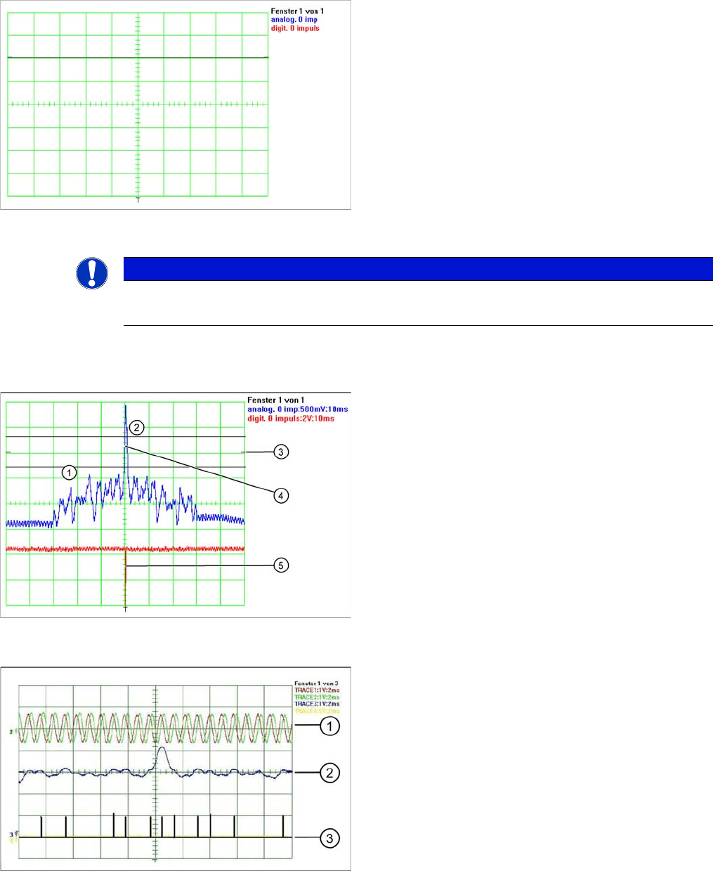
Correctly adjusted read unit
1. There should be no interference pulse in the toler-
ance space of - 0.3 V.
2. The analog zero pulse has to exceed the switching
threshold by more then 0.3V
3. Initial position
4. Analog zero pulse
5. Digital zero pulse
Incorrectly adjusted read unit or contaminated zero pulse
1. Analog track signal A and B
2. Analog zero pulse
3. Digital zero pulse