00194440-10_SM_X-Series_Customer_en.pdf - 第53页
Service Work 3.1.3 Replacing the Motor Circuit Breaker with Motor Pr otection Tripping Unit Electrics and Control Service Manual SIPLACE X Series 53 3.1.3 3 . 1 . 3 R e p la c in g t h e M o t o r C ir c u it B r e a k e…
Service Work
Electrics and Control 3.1.2 Configuring the Input Voltage at the Inrush Current Limitation Board
52 Service Manual SIPLACE X Series
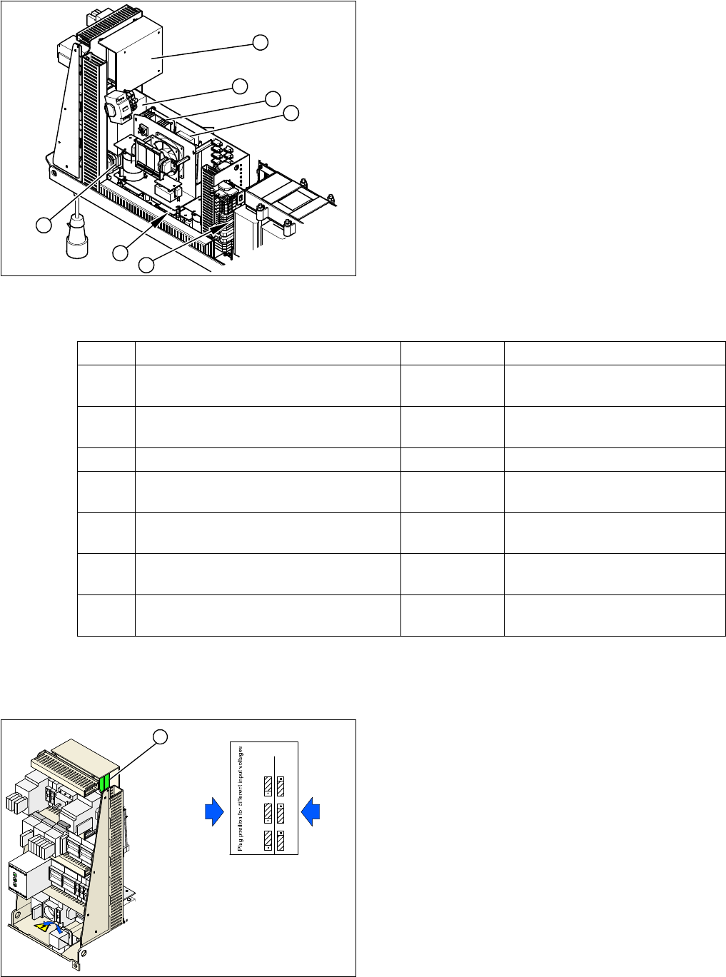
Power supply at the side
Measuring voltages
(*) According to the customer network supply voltage
3.1.2
3.1.2 Configuring the Input Voltage at the Inrush Current Limitation Board
Configuring the Input Voltage at the Inrush Current Limitation Board
1. Terminal panel X100
2. Rectifier U1 to U11
3. Line filter
4. Inrush current limitation board
5. DC/DC converter 24 V (behind the cover)
6. DC/DC converter 5V/24V (behind the cover)
7. Position of fuses F21 to F142
6
5
7
4
3
2
1
Item Designation Contacts Voltage
1 Terminal panel X100 L1, L2, L3 3 x 204 VAC / 3 x 380 VAC
3 x 400 VAC / 3 x 415 VAC (*)
Micro fuse F21, F22, F23 (T 6A, 3A) dis-
charge throttle L20
1, 2 3 x 204 VAC / 3 x 380 VAC
3 x 400 VAC / 3 x 415 VAC
Fuse F61, F62 Rectifier U4 1, 2 3 x 28 VAC
Microfuse F81, F82 (T 10A)
Rectifier U5
1, 2 3 x 23.8 VAC
Micro fuse F111, F112 (T 1A)
Rectifier U8
1, 2 3 x 23.8 VAC
Micro fuse F131, F132 (T 4A)
Rectifier U10
1, 2 3 x 19.7 VAC
Micro fuse 141, F142 (T 6A, 3A)
Rectifier U11
1, 2 3 x 18.7 VAC
1. Inrush current limitation board
X1, X2, X3: plug-in jumpers to configure the inrush cur-
rent limitation
The inrush current limitation board must be configured in
line with the supply voltage. This is performed with the
help of plug-in jumpers on the inrush current limitation
board (1).
► Check the jumper arrangement and correct if neces-
sary.
Take note of the position of jumper J1 (see "6.1.1 In-
rush Current Limitation Board Transformer (A1)
[03066830-xx]" [ ➙ 363]).
X1
X2
X1
X2
X3X3
400 230
Input voltage
3 x 380 V~
3 x 400 V~
3 x 415 V~
3 x 204 V~
3 x 230 V~
1
Service Work
3.1.3 Replacing the Motor Circuit Breaker with Motor Protection Tripping Unit Electrics and Control
Service Manual SIPLACE X Series 53
3.1.3
3.1.3 Replacing the Motor Circuit Breaker with Motor Protection Tripping Unit
Replacing the Motor Circuit Breaker with Motor Protection Tripping Unit
Overview
► Select the required chapter:
▪ "3.1.3.1 Replacing the Motor Circuit Breaker PKZ2 [00342494-xx]" [ ➙ 53]
▪ "3.1.3.2 Replacing the Motor Protection Tripping Unit (PKZ 2)" [ ➙ 54]
▪ "3.1.3.3 Replacing the Motor Circuit Breaker PKE32/XTU-32 [03098183-xx]" [ ➙ 56]
3.1.3.1
3.1.3.1 Replacing the Motor Circuit Breaker PKZ2 [00342494-xx]
Replacing the Motor Circuit Breaker PKZ2 [00342494-xx]
Parts, equipment and tools
▪ Motor circuit breaker PKZ2, basic device 3 pin. [00342494-xx]
A motor protection tripping unit belongs to this:
– Motor protection tripping unit ZM-32-PKZ2 (US version) [00342496-xx]
– Motor protection tripping unit ZM-16-PKZ2 (all except US) [00342495-xx]
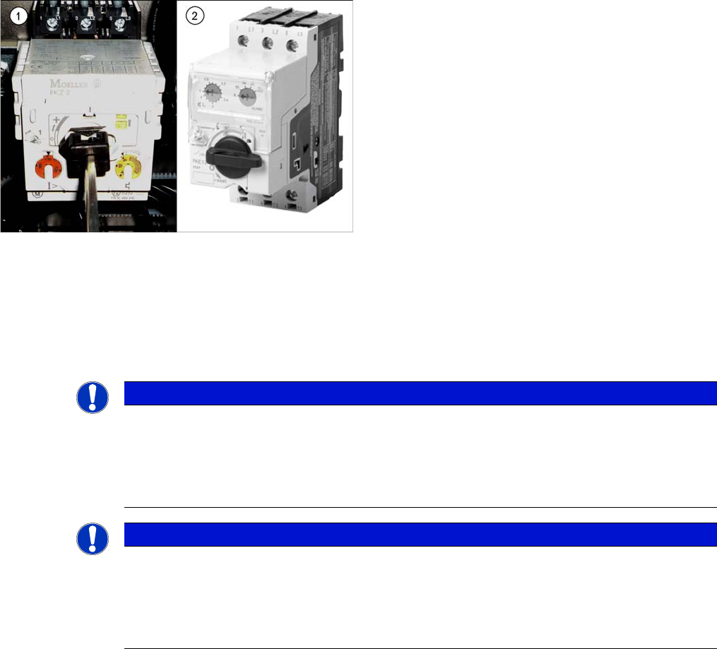
1. Motor circuit breaker – old version with motor protec-
tion tripping unit
2. Motor circuit breaker – new version without motor
protection tripping unit
NOTICE
Old version [00342494-xx]
This version of the motor circuit breaker is obsolete and may need to be replaced with the new
version "Motor circuit breaker PKE32/XTU-32 assembly 3-pin" [03098183-xx].
► Please also read section "3.1.3.3 Replacing the Motor Circuit Breaker PKE32/XTU-32
[03098183-xx]" [ ➙ 56].
NOTICE
Motor protection tripping unit
The corresponding motor protection tripping unit belongs to the motor circuit breaker.
► For details about replacing the motor protection tripping unit, refer to section "3.1.3.2 Re-
placing the Motor Protection Tripping Unit (PKZ 2)" [ ➙ 54]. Pay particular attention to the
correct settings.
Service Work
Electrics and Control 3.1.3 Replacing the Motor Circuit Breaker with Motor Protection Tripping Unit
54 Service Manual SIPLACE X Series
Overview
Removal
► Switch off the machine, disconnect it from the power supply and secure it to prevent unauthorized
reactivation. Observe the instructions in section "1.2 Preparatory Work..." [ ➙ 15].
► Unplug all connections to the motor circuit-breaker. You may want to mark their positions, to make
clear assignment easier later on.
Installation
► Follow the removal instructions in reverse order for installation.
3.1.3.2
3.1.3.2 Replacing the Motor Protection Tripping Unit (PKZ 2)
Replacing the Motor Protection Tripping Unit (PKZ 2)
Parts, Equipment and Tools
If you have supply voltages of 3x208 V~ and 3x230 V~, you will need to use the motor protection tripping
unit ZM-32-PKZ2 [00342496-xx].
▪ Motor protection tripping unit ZM-16-PKZ2 [00342495-xx] (default)
▪ Motor protection tripping unit ZM-32-PKZ2 [00342496-xx] (US version)
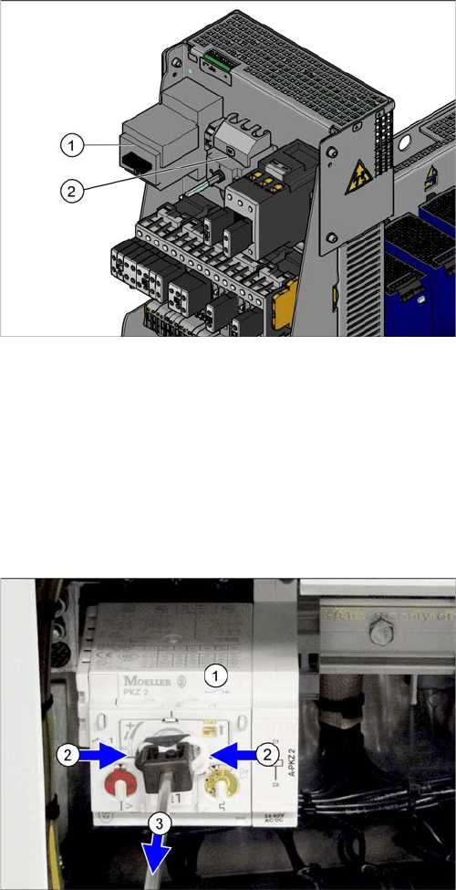
Motor circuit breaker and main switch (using example of
US version)
1. Motor circuit breaker
2. Main switch (US version only)
In non-US versions, the motor circuit breaker also serves
as the main switch.
► Remove the rod which connects the motor circuit
breaker (1) to the outer main switch handle. To do
this, press the white plastic clips together (2) and pull
off the rod (3).
► Take the motor circuit breaker off the rail.