00194440-10_SM_X-Series_Customer_en.pdf - 第118页
Service Work Gantries 3.3.8 Replacing the Trailing Cable 118 Service Manua l SIPLACE X Series Installation ► If you replace a trailing cable which is o f version 1 from B-079-B with a trailing cable which is of ver - s i…
Service Work
3.3.8 Replacing the Trailing Cable Gantries
Service Manual SIPLACE X Series 117
► Disconnect the hoses from the pneumatic distributor (7).
► Undo the four screws (6) fastening the trailing cable console and carefully remove the complete trail-
ing cable from the machine. The fastening screws have been secured with Loctite.
► When you replace an old trailing cable with a new one, you also need to remove the hotlink card
(including fixtures) and the Vision board spread spectrum.
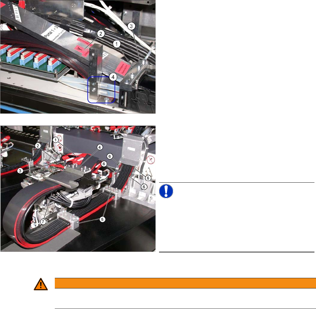
► Loosen the screws fastening the trailing cable mount
(3) .
► If the option "Vacuum pump" is available, loosen the
pneumatic hoses (2) and follow the instructions in the
Retrofit Guide Vacuum Pump[00195089-01].
► Secure the end of the trailing cable (with cable ties) in
the machine to prevent it hanging loosely and damag-
ing other machine components.
► Disconnect the flat ribbon cable (1) from the head
board (2).
► Disconnect the camera cable (3) from the head board
(2).
► Undo the screws fastening the X trailing cable clamp
(4) and the two clamps (5) on the back of the gantry.
NOTICE!
Clamp remains intact
Only loosen the fastening screws. The clamps for the flat
ribbon cable remain in place.
Mark the installation position of the contact disks and
spacer bolts and take care not to lose them. These will
need to be correctly replaced later.
WARNING
Risk of injury to hands
► Use the hose unlocking tool to remove the hoses [03047090-xx].
Service Work
Gantries 3.3.8 Replacing the Trailing Cable
118 Service Manual SIPLACE X Series
Installation
► If you replace a trailing cable which is of
version 1 from B-079-B
with a trailing cable which is of
ver
-
sion 2 after B-079-B
, first replace the new "Vision hotlink adapter VHA assembly" [03054633-xx] and
the "Vision board spread spectrum (VBSX) assembly." [03054634-xx].
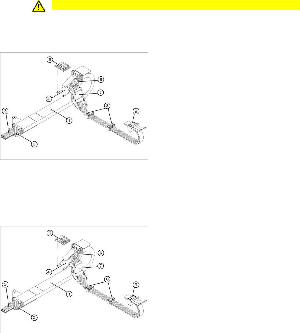
► Carefully insert the new trailing cable (1) into the prescribed position. Make sure you do not twist it.
► Temporarily fasten the ends to the machine base (e.g. by tying them).
► Fit the gantry interface board (5) onto the holder (4) of the new trailing cable.
► Reconnect all compressed air connections at the pneumatic distributor. Observe the correct con-
nector assignment.
► The pneumatic hoses need to be shortened to the optimum length, with the help of the gauge. See
also "3.3.8.7.2 Preparing the Trailing Cable" [ ➙ 112]. They must engage firmly but should not be
folded over.
► Loosely screw in the clamps (8) and (9).
► Check that the power track chain can run along the top of the machine base without obstruction.
Move the Y axis back and forth to check this.
► If necessary, correct at the trailing cable console (7) and at the clamps (8) and (9).
CAUTION
Handling
Handle the new trailing cable with care and enlist the help of a second person.
Make sure that the flat ribbon cable and the pneumatic hoses are not rubbed against any parts
or folded. Look out for sharp edges.
1. Complete trailing cable unit
2. Mount
3. Pneumatic hoses (shorten to optimum length with
gauge)
4. Gantry interface bracket
5. Gantry interface
6. Connection piece for cooling tubes to Y motor
7. Trailing cable console
8. Clamp at back of gantry
9. X trailing cable clamp
► Loosely fasten the trailing cable console (7) with a
screw.
► Clean the trailing cable contact surface on the ma-
chine base with a dry cloth.
► Starting from the trailing cable console (7), run all ca-
bles and hoses to the appropriate connections:
► Reconnect all electrical connections at the head
board. Observe the correct connector assignment.
► Reestablish all connections to the hotlink card and
the Vision board spread spectrum.
Service Work
3.3.8 Replacing the Trailing Cable Gantries
Service Manual SIPLACE X Series 119
► Fix the two clamps (8) and (9) and the trailing cable console (7). Use Loctite 241 to secure them.
► Tighten the fastening screws for the trailing cable console (7) crosswise.
See also
3.3.8.4 Handling the Hose Unlocking Tool [03047090-xx] [ ➙ 99]
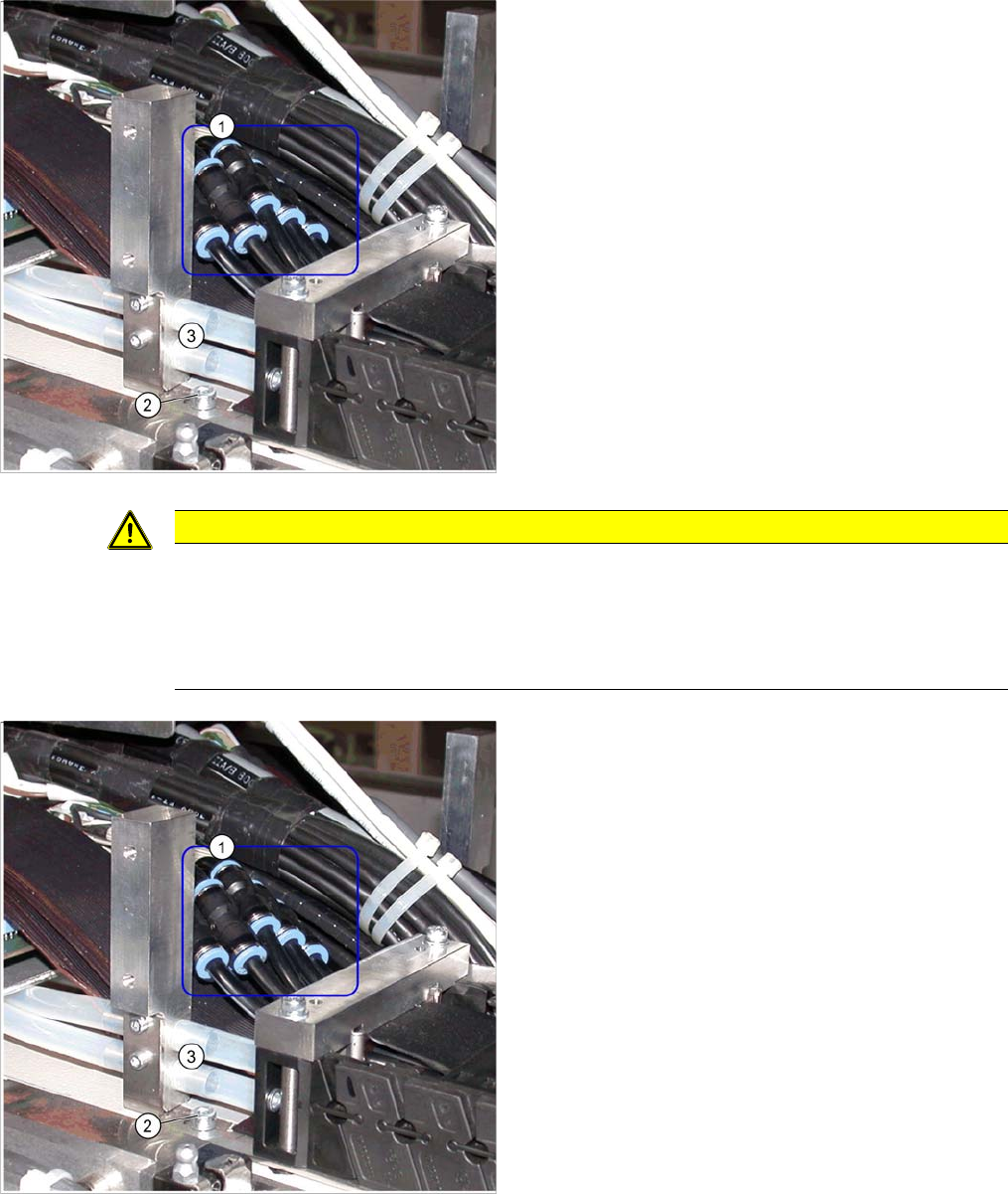
► Fit the trailing cable mount (2) onto the machine
base.
Connect the pneumatic hoses to the pneumatic distribu-
tor in the machine base.
The pneumatic hoses are run to the pneumatic distributor
in the machine base. The existing pneumatic hoses,
which are run in the machine, need to be severed and
connected to the trailing cable (1) at the exact position,
with the help of hose couplings [03049770-01].
► Place the gauge at the stopper edge of the mount and
label the pneumatic hoses for the trailing cable. See
also "3.3.8.7.2 Preparing the Trailing Cable" [➙112].
CAUTION
Shortening and connecting the pneumatic hoses
► Label the order of pneumatic hoses (from 1 to 7 – inside to outside). This is important to
ensure that the hoses are then correctly connected again after cutting.
► Make sure that you use the correct gauge for your gantries and that you do not cut the pneu-
matic hoses too short.
► Cut the pneumatic hoses of the new trailing cable at
the marked points.
► The seven hoses of the new trailing cable are con-
nected to one another. Carefully separate these from
one another, up to the mount.
► Connect the pneumatic hoses for the trailing cable
with the hose couplings (1). Observe the labeling (1-
7 from inside to outside).
► Reconnect the Y motor cooling tubes to the connec-
tion pieces.
► If you have the "Vacuum pump" option, reconnect the
pneumatic hoses.
► Fasten new cable ties at the original points.
► Replace all dismantled cover plates in their original
positions.