00194440-10_SM_X-Series_Customer_en.pdf - 第120页
Service Work Gantries 3.3.9 Fitting and Removing the Y Axis Bumper 120 Service Manua l SIPLACE X Series 3.3.9 3 . 3 . 9 F it t in g a n d R e m o v in g t h e Y A x is B u m p e r Fitting and Removi ng the Y Axis Bumper …
Service Work
3.3.8 Replacing the Trailing Cable Gantries
Service Manual SIPLACE X Series 119
► Fix the two clamps (8) and (9) and the trailing cable console (7). Use Loctite 241 to secure them.
► Tighten the fastening screws for the trailing cable console (7) crosswise.
See also
3.3.8.4 Handling the Hose Unlocking Tool [03047090-xx] [ ➙ 99]
► Fit the trailing cable mount (2) onto the machine
base.
Connect the pneumatic hoses to the pneumatic distribu-
tor in the machine base.
The pneumatic hoses are run to the pneumatic distributor
in the machine base. The existing pneumatic hoses,
which are run in the machine, need to be severed and
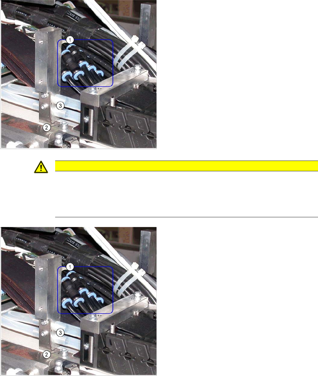
connected to the trailing cable (1) at the exact position,
with the help of hose couplings [03049770-01].
► Place the gauge at the stopper edge of the mount and
label the pneumatic hoses for the trailing cable. See
also "3.3.8.7.2 Preparing the Trailing Cable" [➙112].
CAUTION
Shortening and connecting the pneumatic hoses
► Label the order of pneumatic hoses (from 1 to 7 – inside to outside). This is important to
ensure that the hoses are then correctly connected again after cutting.
► Make sure that you use the correct gauge for your gantries and that you do not cut the pneu-
matic hoses too short.
► Cut the pneumatic hoses of the new trailing cable at
the marked points.
► The seven hoses of the new trailing cable are con-
nected to one another. Carefully separate these from
one another, up to the mount.
► Connect the pneumatic hoses for the trailing cable
with the hose couplings (1). Observe the labeling (1-
7 from inside to outside).
► Reconnect the Y motor cooling tubes to the connec-
tion pieces.
► If you have the "Vacuum pump" option, reconnect the
pneumatic hoses.
► Fasten new cable ties at the original points.
► Replace all dismantled cover plates in their original
positions.
Service Work
Gantries 3.3.9 Fitting and Removing the Y Axis Bumper
120 Service Manual SIPLACE X Series
3.3.9
3.3.9 Fitting and Removing the Y Axis Bumper
Fitting and Removing the Y Axis Bumper
3.3.10
3.3.10 Replacing the X Scale
Replacing the X Scale
3.3.11
3.3.11 Replacing the Y Scale
Replacing the Y Scale
CAUTION
Y axis bumper
The Y axis bumpers may only be removed or replaced by the SIPLACE Service team.
NOTICE
Service Work Conveyor
This service task may only be performed by specially trained SIPLACE service technicians. The
procedure is described in a separate manual.
NOTICE
Service Work Conveyor
This service task may only be performed by specially trained SIPLACE service technicians. The
procedure is described in a separate manual.
Service Work
3.3.12 Replacing the Head Adaptor on the Pick&Place Module [03000902-xx] Gantries
Service Manual SIPLACE X Series 121
3.3.12
3.3.12 Replacing the Head Adaptor on the Pick&Place Module [03000902-xx]
Replacing the Head Adaptor on the Pick&Place Module [03000902-xx]
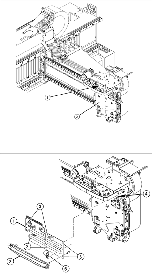
Overview
Removal/installation
1. Head adapter P&P
2. Head plate
1. Head adapter
2. Cable clamps (consisting of upper and lower part)
3. Fastening screws
4. Spacers
5. Hose fixture
► Remove the upper part of the cable clamp (2).
► Unplug both flat ribbon cables to the P&P modules
from the head adapter (1).
► Undo the 6 fastening screws (3).
► Loosen the hose mount (5) and the spacers, (4)
where necessary.
► Carefully pull the head adapter (1) down and out and
dismantle the lower part of the cable clamp, if neces-
sary.
► Fit the new head adapter with the lower part of the ca-
ble clamp and reconnect to the electrical system.
► Fit the cable clamp assembly and attach the hose
mount.
► Make sure that the cables are seated firmly during
axis movement and that no sections of them will be
subject to wear or damage.