00194440-10_SM_X-Series_Customer_en.pdf - 第185页
Service Work 3.6.18 Replacing the Conveyor Control Assembly [03071908 - xx] Modular PCB Conveyor System Service Manual SIPLACE X Series 185 Overview Removal ► If possible, make a backup of the MA data from the old convey…
Service Work
Modular PCB Conveyor System 3.6.18 Replacing the Conveyor Control Assembly [03071908-xx]
184 Service Manual SIPLACE X Series
3.6.18
3.6.18 Replacing the Conveyor Control Assembly [03071908-xx]
Replacing the Conveyor Control Assembly [03071908-xx]
Jumper settings for quad lane
▪ J1, J2 (ao, ap): position 2-3 (SMEMA active)
▪ J3 (ao, ap): position 1-2 (emergency stop loop, not used)
▪ J7 (ao): position 1-2 (CAN bus OFF) (not available for conveyor control TSP301E)
▪ S4 (not available for conveyor control TSP301E):
Parts
The conveyor control (TSP) version required will vary according to the conveyor type concerned (TSP):
▪ Control assembly for single conveyor [00365543-xx]
▪ Control assembly for dual conveyor [00365544-xx]
▪ Control assembly for quad lane conveyor [03071908-xx]
NOTICE
Quad lane
Quad lane conveyors also need the "PCB SMEMA quad lane board" [03067662-xx] and the
SMEMA adapter "SMEMA interface quad lane" [03067541-xx].
These are interfaces which divide the four standard interfaces into eight interfaces.
► When replacing individual boards, make sure that the connection cables are marked and
then reconnected to the boards in their original configuration.
► Pay particular attention to the correct jumper settings.
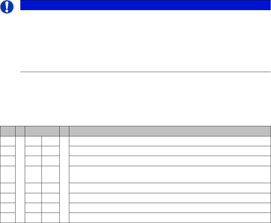
S S4 Comment
1ON ON
2OFFON: D4 – OFF: SIPLACE X, HF, D3, X4I
3 OFF OFF: Clamping sensor (not used since SW 505)
4ON ON: SIPLACE X2, X3, X4 , X4I (Quad Lane conveyor)
OFF: SIPLACE X2, X3, X4, HF, D4, D3 (standard conveyor)
5OFFNot used
6ON OFF: Standard conveyor – ON: Quad Lane conveyor
7OFFNot used
8OFFNot used
Service Work
3.6.18 Replacing the Conveyor Control Assembly [03071908-xx] Modular PCB Conveyor System
Service Manual SIPLACE X Series 185
Overview
Removal
► If possible, make a backup of the MA data from the old conveyor control (TSP).
► Switch off the machine.
► Mark all connections on the conveyor control (TSP), so that these can be easily allocated again later
on.
► Loosen all connections on the conveyor control (TSP).
► Remove the conveyor control (TSP) from the machine.
Installation
► Fit the new conveyor control (TSP) in the reverse order.
► Import the MA data back into the conveyor control (TSP). Either use the data saved before removal
or the last backup version.
► Then perform a function test.
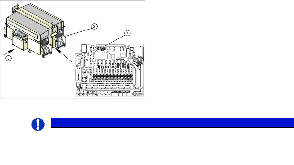
Access to conveyor control (here the example of an X4)
1. Conveyor Control TSP 301
2. Access to conveyor control
3. Transport direction
The TSP 301 conveyor control (1) is situated on the right
side of the middle section of the machine (2) (together
with the pneumatic unit). The conveyor control is secured
with a lockable door.
For terminal assignment details, please refer to the cur-
rent version of the circuit diagram folder for the relevant
machine.
NOTICE
MA data on the station computer
The current MA data are saved on the TSP (conveyor control).
► The machine data for the conveyor is saved with the other data in the SW70x.
► SW 60x: Perform a backup of this data at the station computer, at C:\Srcma.
Service Work
Modular PCB Conveyor System 3.6.19 Replacing and Teaching the Sonar Sensor PXS240 (QC) [03069863-xx]
186 Service Manual SIPLACE X Series
3.6.19
3.6.19 Replacing and Teaching the Sonar Sensor PXS240 (QC) [03069863-xx]
Replacing and Teaching the Sonar Sensor PXS240 (QC) [03069863-xx]
All sonar sensors used can be disconnected for replacement and dismantled from the assembly bracket.
Parts, equipment and tools
▪ Standard tool
▪ Setting gauge for sonar sensor (proximity switch) [03048764-xx]
▪ Programming cable for PXS240 sensor [03073330-xx]
▪ Sonar sensor PXS240 [03069863-xx]
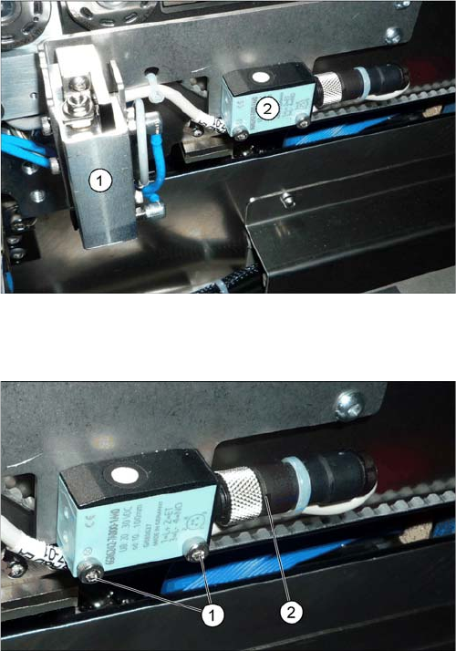
Overview
Removal/installation
1. PCB stopper
2. Ultrasonic sensor PXS240
► Loosen the screws (1) fastening the ultrasonic sen-
sors.
► Unscrew the press fit connection (2) from the sonar
sensor.