YSP20_Users_E.pdf - 第106页
4-14 4 aily operation 6.3 Long-term storage tasks If the solvent pump is not used for extended periods (about 6 months or more), then it ma y dry out internally and cause operating defects. T he solvent path within the…
4-13
4
aily operation
4
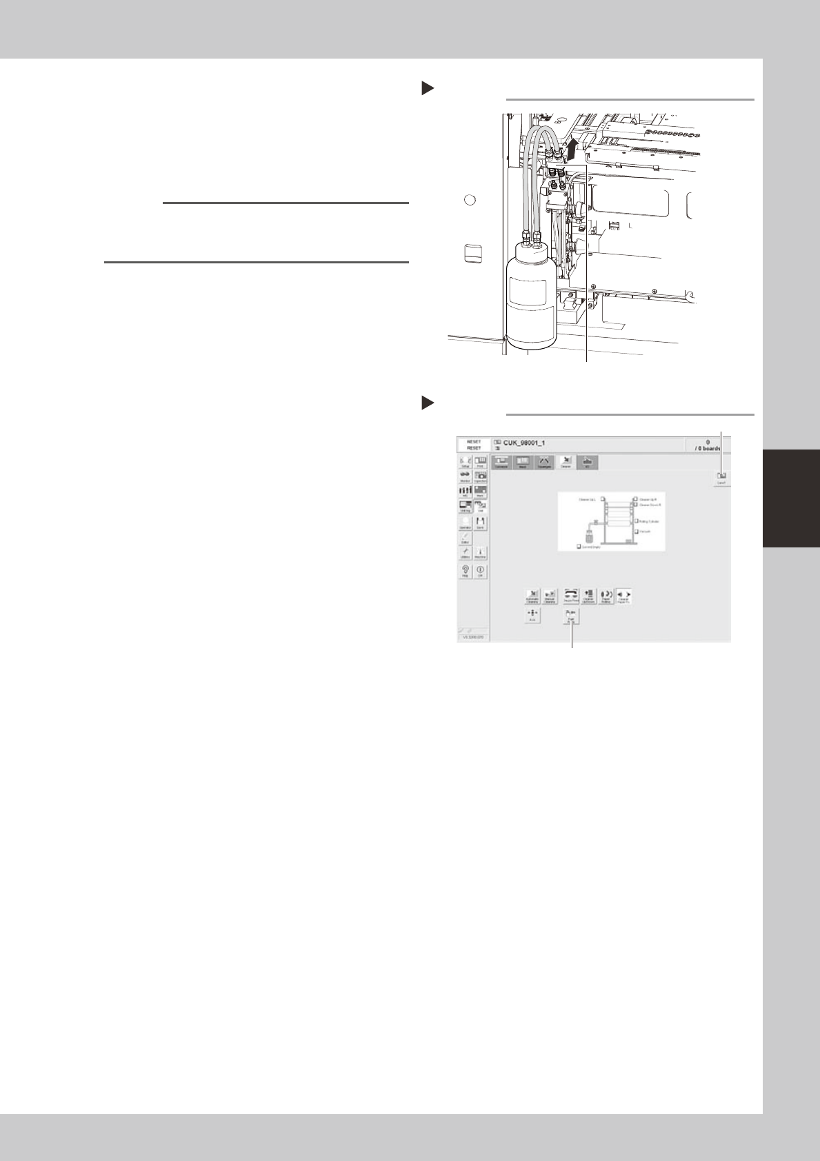
Disconnect the refill tool.
When the tank has been refilled with the
solvent completely, the solvent supply from
the refill tool is stopped automatically.
Disconnect the refill tool from the joint.
63412-N3-00
n
NOTE
When removing the refill tool, hold the bottle upright as
shown on the right so that the solvent does not leak
out.
5
Close the cover and press the
[READY] button.
6
Supply the solvent to the solvent
arrival sensor.
1. Select the [Cleaner] tab on the [Unit]
screen.
2. Press the [Solvent Pump] button to supply
the solvent to the solvent arrival sensor.
3. Stop the pump when the solvent seeps
out to the gauze roll.
64408-N3-00
7
Check the solvent supply status.
Check that the yellow signal lamp on the
top of the machine is off and the "ERROR"
sign in the status area on the operation
screen has disappeared.
Disconnecting the nozzle
Step 4
Pull and disconnect the nozzle from the joint.
Solvent pump
Step 6
Press this button.
[Lane] button
4-14
4
aily operation
6.3 Long-term storage tasks
If the solvent pump is not used for extended periods (about 6 months or more), then it may dry out internally
and cause operating defects. The solvent path within the pump must be blocked to prevent this from happening.
The path blocking procedure is described below.
n
Blocking the solvent path
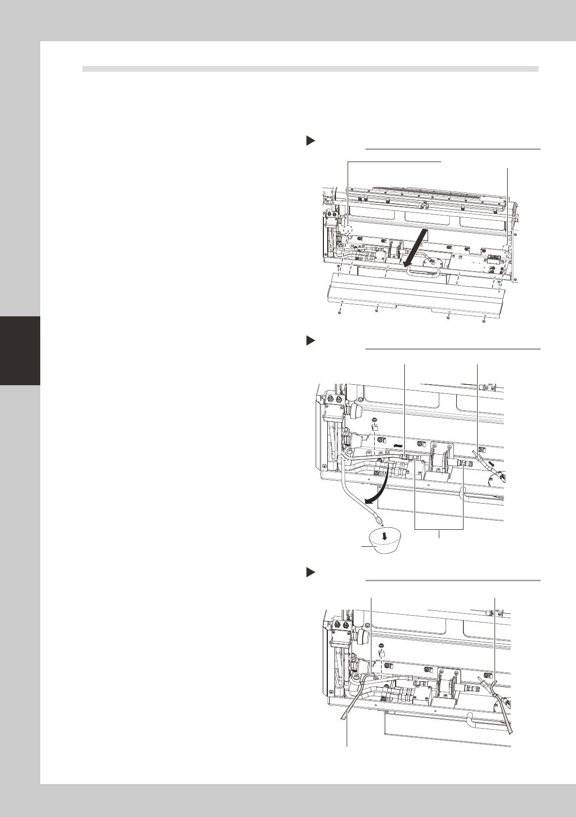
1
Remove the cleaner cover.
1. Loosen the two screws (enclosed by a
dashed line circle in the figure on the
right) clamping the rear side of the
cleaner cover. (No need to remove
them)
2. Next remove the screws at 4 locations on
the near side (see drawing).
3. Raise the cover upward and then pull
toward you to remove it.
63413-N3-00
2
Remove the joints.
Remove the joints from two locations, one
on the head side and the other on the tank
side from the shut-off valve joint. Use caution
because alcohol remaining in the hose will
come out when the joint on the head side is
removed.
1. Remove the head side joint in the bent
state as shown by the dashed line in the
figure on the right.
2. Prepare a container, free the bent
location and let the alcohol drain into
the container.
3. Remove the tank side joint and then
quickly point it upward to let the alcohol
in the hose return back to the tank.
63414-N3-00
3
Mark the hoses you removed.
Mark the two hose sections you removed in
step 2 by winding yellow ribbon or a similar
item around them.
63415-N3-00
4
Reattach the cleaner cover.
Reinstall the cleaner cover in the reverse of
the procedure that you removed it in step 1.
Place a ribbon on the outer side of the
cover so that others will know that the joints
were removed.
n
Resetting operation
Connect the hoses in the reverse of the "Blocking the
solvent path" procedure and refill with solvent by
referring to 6.2 "Refilling the solvent". When finished
refilling, operate the solvent pump to make sure it
operates correctly.
Removing the cleaner cover
Step 1
First loosen these two screws.
Removing the joints
Step 2
Joint (to head)
Shut-off valve joint
Container
Joint (to tank)
Hose markings
Step 3
Marking (yellow ribbon, etc.) Marking
As seen from outside the cover
4-15
4
aily operation
7. Setting up the mask and squeegee
This section explains procedures for clamping the mask (stencil) you have prepared on the printing table and
installing the squeegee onto the squeegee head.
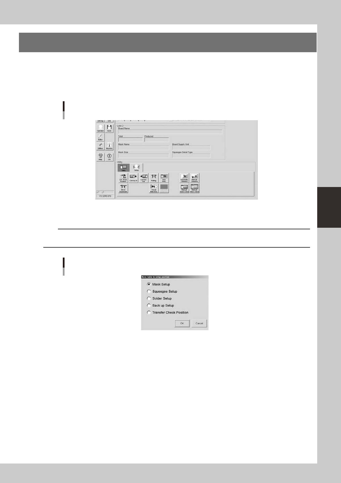
1
On the Setup screen, open the [Setup] tab under “Utility”.
The buttons on this screen are used in the following steps to change the mask and squeegee setup.
Setup screen
[Setup] tab
64425-N3-10
2
Press the [SW. Prod. Position] button and select “Mask Setup”.
n
NOTE
When both lanes are used for production, the dialog box for selecting the lane number appears, so select the lane.
The lane currently used in production is grayed out.
Dialog box for move table to setup position
64426-N3-00