YSP20_Users_E.pdf - 第274页
A-2 Appendix 1.2 Power connection terminals T he power connection terminals are located inside the lower right panel on the front of the machine. Connect the power cable leads as shown belo w to the L1, L2, L3 and ground…
A-1
Appendix
1. Specifications
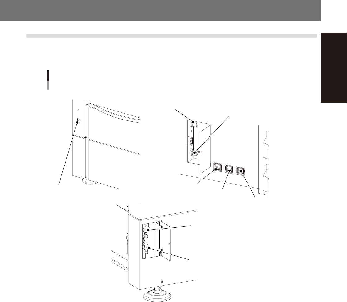
1.1 Air regulator unit
The air regulators and related components for controlling the air pressure to the pneumatic units of this
machine are located on the front and rear of the machine. The air pressure regulator must be correctly set to
supply the machine at an optimum air pressure.
Air regulator unit
Right-to-left flow machine
Source air connecto
Air supply/shutoff switch
■ Front left side of machine ■ Rear upper left of machine
■ Rear lower left of machine
Main pressure
gauge (1)
Main pressure
gauge(2)
Edge clamp pressure gauge
Main air pressure regulator (1)
Main air pressure regulator (2)
Cleaner negative
pressure gauge
53A01-N3-00
n
Supply air pressure
This is the pressure of the source air supplied to the machine. Before setting the air pressure with the air regulator, make
sure that this supply air pressure is in the following optimal range.
YSP20 : 0.45MPa
n
Air pressure display
Set air pressure level: 0.40MPa to 0.41MPa
This is shown in green when the pressure is normal, and turns red if a pressure drop is detected.
n
Edge clamp pressure gauge
Shows the edge clamp air pressure.
n
Cleaner negative pressure gauge
Shows the cleaner's vacuum air pressure level (negative pressure level).
n
Air supply/shutoff switch (valve)
Turning this switch to the right shuts off air supply and exhausts air that remains inside the machine.
n
Source air connector
Prepare an air hose with an inside diameter of at least 8 mm having a 30SH socket (Nitto Koki), and connect it to this
connector. Use dry and clean air that has been passed through the air dryer and air filter.
A-2
Appendix
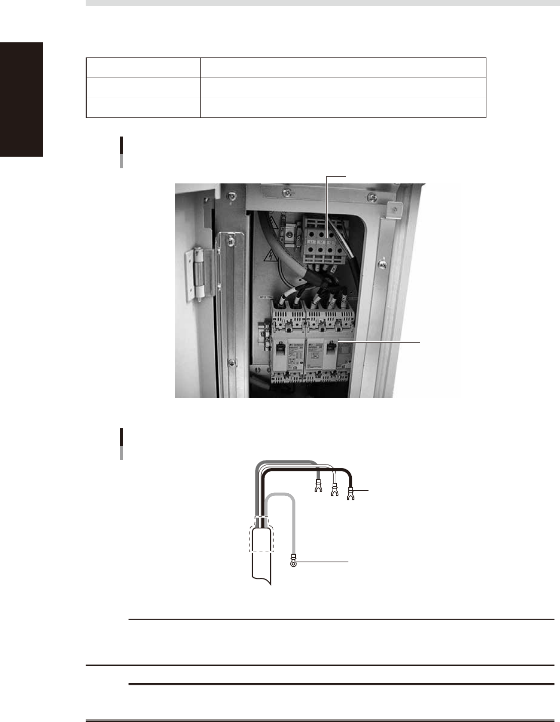
1.2 Power connection terminals
The power connection terminals are located inside the lower right panel on the front of the machine. Connect
the power cable leads as shown below to the L1, L2, L3 and ground terminal (PE) on the power terminal block.
n
Power supply specifications
Power 3-phase AC 200 / 208/ 220 / 240 / 380 / 400 / 416V ±10%
Frequency 50/60Hz
Power capacity 7.0KVA
Power connection terminals
Power input terminal (L1, L2, L3, PE)
Main breaker
53A02-N3-00
Power cable example
L1
U
L2
V
L3
W
Earth
Green
L=100mm
L=100mm
Ring tongue terminal
Fork tongue terminal
(vinyl-insulated)
53A03-N3-00
c
CAUTION
Use a power cable with a grade of AWG10 (cross-sectional area of the conductor is 5.5 mm
2
) or more.
Make sure that the power cable connections are correct. If misconnected, the vacuum operation of the suction unit
will be reversed (air blows outward).
w
WARNING
TO AVOID THE RISK OF ELECTRICAL SHOCK, MAKE SURE THAT THE POWER SOURCE IS OFF BEFORE CONNECTING THE
POWER CABLE. ALSO MAKE SURE THAT THE GROUND CABLE IS SECURELY CONNECTED TO THE MACHINE.
A-3
Appendix
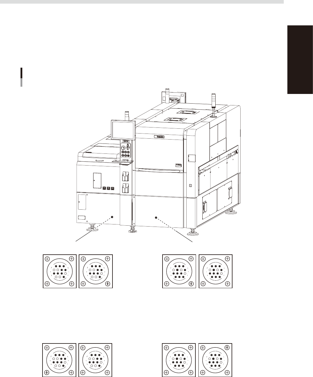
1.3 Connection between machines
To exchange signals such as board request and operation status with the downstream or upstream machine, the
"NEXT INTERFACE" and "PREVIOUS INTERFACE" connectors located on the rear of the machine are used. The
"NEXT INTERFACE" connector connects to the downstream machine, and the "PREVIOUS INTERFACE"
connector connects to the upstream machine such as a loader. In the case of standard right-to-left flow, the
PREVIOUS INTERFACE connector is located inside the lower left panel on the rear of the machine while the
NEXT INTERFACE connector is located inside the lower right panel on the rear of the machine. Both connectors
use an AMP 206043-1 (14-pin receptacle).
PREVIOUS INTERFACE NEXT INTERFACE
Machine-to-machine interface connectors
Right-to-left flow machine
Connector : AMP 206043-1 (14-pin receptacle)
Connector : AMP 206043-1 (14-pin receptacle)
14
11
12
7
4
8
3
1
14
11
12
7
4
8
3
1
14
11
12
7
4
8
1
3
14
11
12
7
4
8
1
3
Lane 1 Lane 2 Lane 1 Lane 2
■ Left-to-right flow machine
PREVIOUS INTERFACE NEXT INTERFACE
14
11
12
7
4
8
3
1
14
11
12
7
4
8
3
1
14
11
12
7
4
8
1
3
14
11
12
7
4
8
1
3
Lane 2 Lane 1 Lane 2 Lane 1
53A04-N3-00