YSP20_Users_E.pdf - 第166页
5-40 5 Creating and setting the data 8. Graphic alignment When finished creating board data and necessar y mark data, you should check to see whether the mask apertures are aligned with the land patter ns on the board, a…
5-39
5
Creating and setting the data
7
Press the [Find Best] button to find an optimum threshold level.
Pressing this button automatically finds an optimum threshold level for the mark, and the result is
displayed. If an error occurs, check the following points.
1. Press the [Cancel] button to return to the Mark screen, and then check whether parameters such as
"Mark Type", "Shape Type" and "Algorithm Type" are correct.
2. Recheck the light levels and make adjustments as needed.
3. Press the [Find Best] button again to find an optimum threshold level.
8
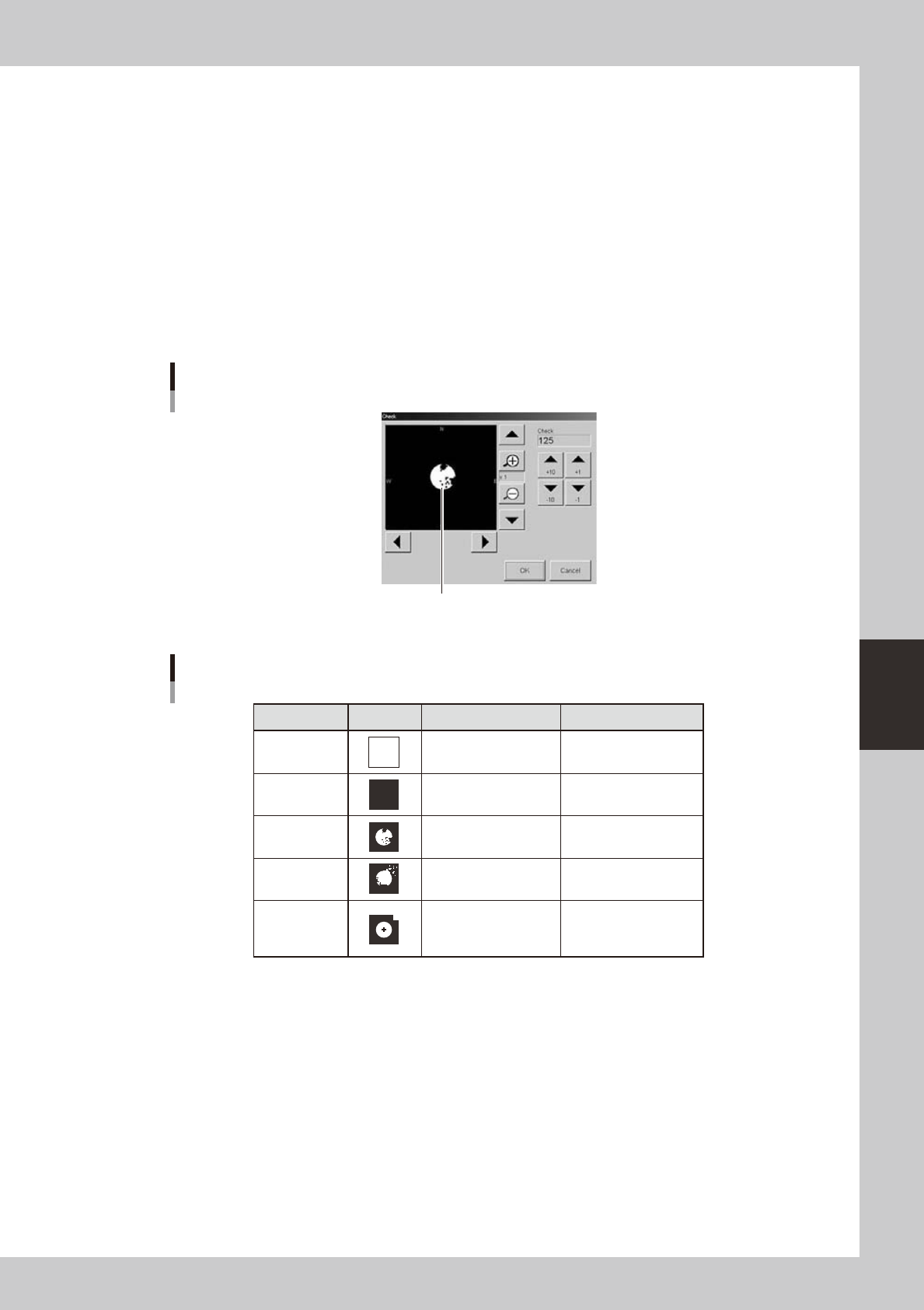
Press the [Test] button to perform the vision test.
When the result is successful, the adjustment is now complete.
If the vision test result is a fail, press the [Result] button to display the binary image of the mark and
adjust the threshold level manually by referring the table below, so that the binary image is most clearly
displayed.
Binary mark image
Binary mark image and threshold level adjustment
64536-N3-00
Binary image check and adjustment
State
All white
All black
Noise within
mark
Noise outside
of mark
Other than
mark in
search area
Image Countermeasure
Increase the threshold
level with the arrow
buttons.
Decrease the threshold
with the arrow buttons.
Increase the Cut Inner
Noise level.
Increase the Cut Outer
Noise level.
Reduce the Search
Area size.
Remarks
Adjust it till the mark is
displayed.
Adjust it till the mark is
displayed.
Refer to "Search Area"
explained previously.
Recognition time becomes
longer as the Cut Inner
Noise level is increased.
Recognition time becomes
longer as the Cut Outer
Noise level is increased.
63526-N3-00
9
Press the [Test] button to perform the vision test again.
Repeat this test several times. If no error is detected, each parameter is appropriate so the adjustment
is now complete.
0
Press the [OK] button to save the adjusted data.
The Mark Adjust screen closes and returns to the Mark screen.
q
Use the same procedure when adjusting other marks.
5-40
5
Creating and setting the data
8. Graphic alignment
When finished creating board data and necessary mark data, you should check to see whether the mask
apertures are aligned with the land patterns on the board, and correct any offsets (positional shifts) as
needed.
n
NOTE
When fiducial marks on the board and mask frame are used, their positions are automatically aligned by vision
recognition, so you can omit "graphic alignment". However, when the fiducial mark positions were defined by
teaching or when the mask aperture shapes are not identical with the land pattern shapes, then position alignment
may not be accurate if only using vision recognition. In those cases, the graphic alignment function allows you to
make position alignment easily and accurately.
l
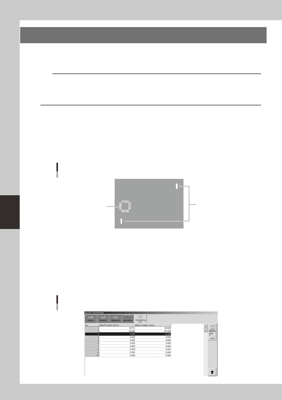
Coordinates used for graphic alignment
1. If the center deviation and rotational deviation exist, specify two diagonal points as shown below.
2. If you want to make alignments at a particular point other than the above two diagonal points, then specify only that
one point after adjusting the rotational deviation of the entire board by specifying the two diagonal points. If two
particular points are specified in this case, the rotational component that has already been adjusted will change, so use
caution.
The coordinates to be specified for graphic alignment should be measured in advance, or if the coordinate data (design
data) is available, make a note of the coordinates in advance.
Specified coordinates for graphic alignment
Specify two diagonal points.
2
1
3
After offset amount is updated
63528-N3-00
1
Load a board on the conveyor.
1. Press the [Setup] button and select the [Setup] tab.
2. Press the [Conveyor In] button and follow the message on the screen to load the board.
2
Temporarily enter the coordinates used for graphic alignment.
1. Press the [Print] button, open the [Squeegee] tab, and press the [Detail Setting] button.
2. Open the [Visual Matching Point] tab.
3. In the ""Adjust Position X" and "Adjust Position Y" fields, enter the coordinates that have been
measured in advance.
Temporarily entering the coordinates for graphic alignment
64541-N3-00
5-41
5
Creating and setting the data
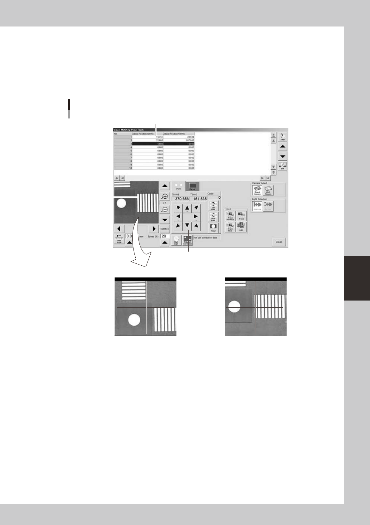
3
Teach the coordinates for graphic alignment.
1. Press the [Teach] button to open the teach window for graphic alignment.
2. Position the cursor on the first coordinates and press the [Trace] button.
3. Using the arrow keys, align the target coordinates (pad) with the center.
4. Press the [Teach] button to teach the coordinates.
Use the same method to teach the second point.
Teach window for graphic alignment
Arrow keys
NG OK
Pad to be aligned
Alignment coordinates
64542-N3-10