YSP20_Users_E.pdf - 第110页
4-18 4 aily operation 7.1 Mask size and mask stopper pin position T he mask stopper pin position must be changed according to the mask frame size to be used as shown belo w . Mask stopper pins are screw types. n Mask f…
4-17
4
aily operation
7
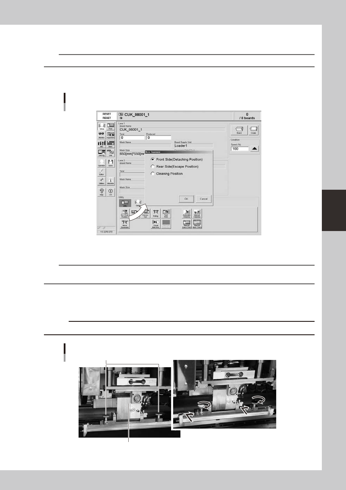
Move the squeegee head to the attach/detach position.
1. After closing the safety cover and pressing the [READY] button, press the [Move Squeegee] button.
TIP
When both lanes are used for production, the dialog box for selecting the print table appears, so select the table.
2. Select the "Front Side" position (attach/detach position) and press the [OK] button.
The squeegee head moves to the front side (towards you).
Squeegee position dialog box
64409-N3-10
8
Press the [SW. Prod. Position] button and select “Mask Setup”.
n
NOTE
When both lanes are used for production, the dialog box for selecting the lane number appears, so select the lane.
The lane currently used in production is grayed out.
Select “Squeegee Setup”. When the DOOR LOCK lamp turns off, open the safety cover.
9
Install the squeegee to the squeegee head.
Fit the mount knobs into squeegee head holder and tighten them as below.
c
Attaching the 3S squeegee
Mount knobs
Squeegee holder
63418-N3-00
4-18
4
aily operation
7.1 Mask size and mask stopper pin position
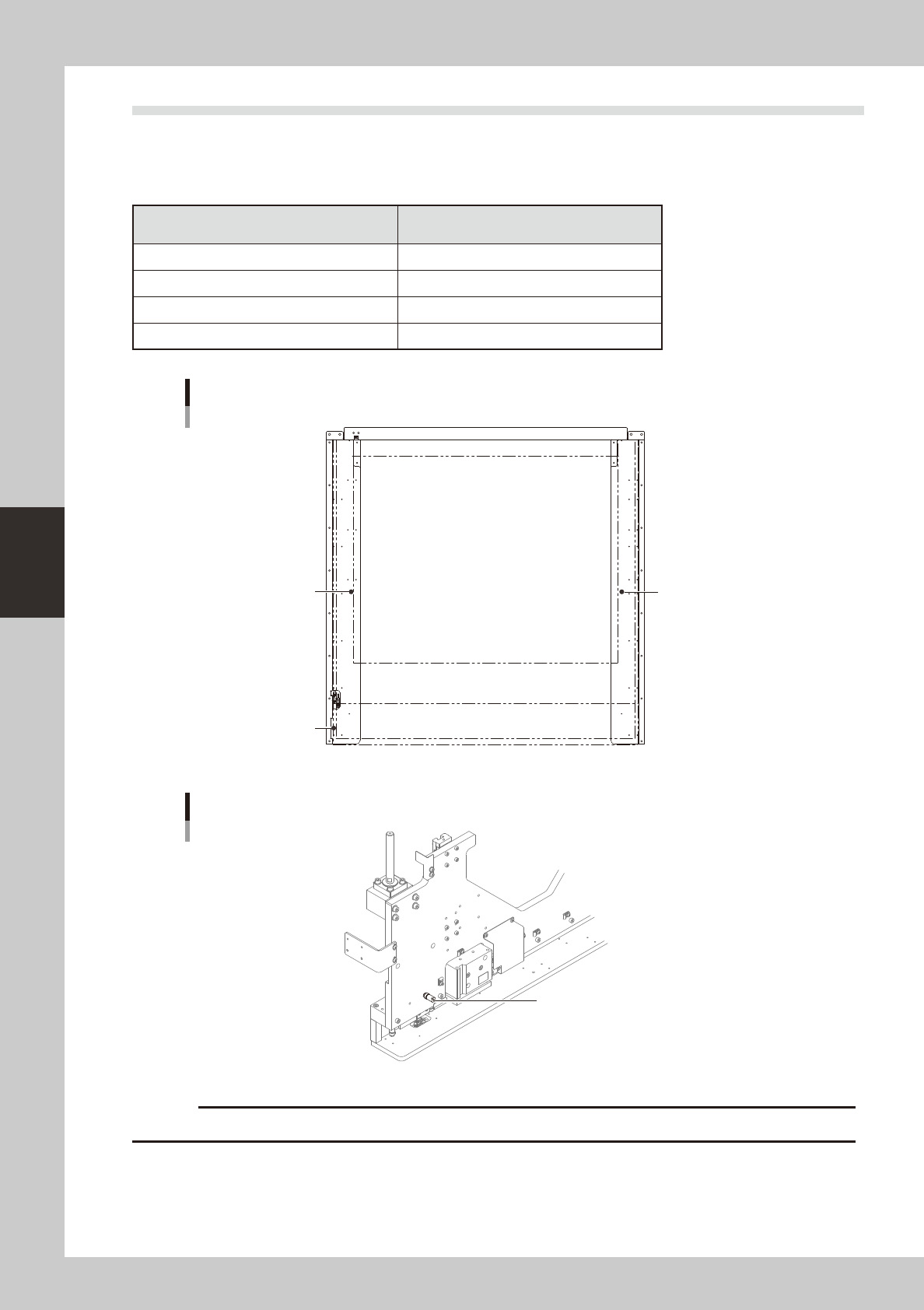
The mask stopper pin position must be changed according to the mask frame size to be used as shown below.
Mask stopper pins are screw types.
n
Mask frame size and stopper pin position
Mask frame size
L (mm) × W (mm)
Mask stopper position
750 × 750 Not used
750 × 650 Not used
736 × 736 1
650 × 550 2&3
Mask size and stopper pin position
1
2
3
63419-N3-00
Mask stopper pin
Mask stopper pin
63420-N3-00
c
Securely tighten the mask stopper pin by hand to prevent it from loosening and falling off.
4-19
4
aily operation
7.2 Mask frame dimensions and mask standard position
n
Mask frame dimensions and mask standard position
Recommended
specifications
Compatible
mask frame size
(mm)
Mask standard position Standard position offset
Setting X direction
Y direction
A: From outside of mask
frame (mm)
B: From center of mask
(mm)
X Y
YSP20
recommended
specifications
L750 × W750
Center
Center
Center 0 0
Front A 145 B 230 0 0
L736 × W736
Center
Center
Center 0 0
Front A 138 B 230 0 0
L650 × W550
Center
Center
Center 0 0
Front A 150 B 125 0 0
Minami Kogaku
recommended
specifications
L750 × W650
Center
Center
Center 0 0
Front A 150 B 175 0 0
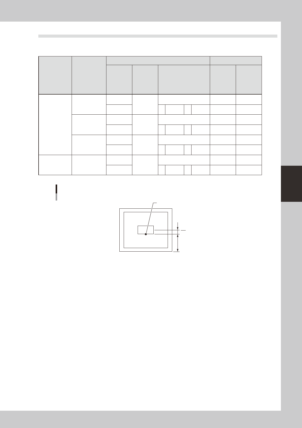
When mask standard position is “Front”
Mask standard position: “Front”
Mask center
A
B
Standard position
63421-N3-00