YSP20_Users_E.pdf - 第44页
1-5 1 Part names and functions 2. Operation panels and data input units Standard machines are equipped with an operation display , operation panel buttons, a keyboard and a mouse on the front and rear (option) of the mac…
1-4
1
Part names and functions
Setup cover
Opening this cover enters a state that allows non-stop changeover. Before opening this cover to change the matrix plate
or backup pins, make sure the DOOR LOCK lamp is OFF. Keep this cover closed during operation.
Pressure gauge, pressure regulator, air supply/shut-off switch
Indicates and adjusts the air pressure supplied to the machine. For details, see Appendix 1.1, "Air regulator unit".
USB port
· Machine for right-to-left flow: USB port is located on the rear left side.
· Machine for left-to-right flow: USB port is located on the front left side.
Connect to this port when using a USB memory to back up board data stored in the machine. Always close this panel
before operating a USB memory after inserting it into the port.
Cleaner negative pressure gauge
Shows the negative pressure for the cleaner.
Rear lower right panel
The machine-to-machine interface connector (labeled “NEXT”), servo controller, I/O board, and relay panel are located
behind this panel. Keep this panel closed during operation.
Rear lower left panel
The machine-to-machine interface connector (labeled “PREVIOUS”) and blower unit (blower motor and inverter) are
located behind this panel. Keep this panel closed during operation.
n
NOTE
For details on the machine-to-machine interface connectors, see Appendix 1.3, “Connection between machines”.
1-5
1
Part names and functions
2. Operation panels and data input units
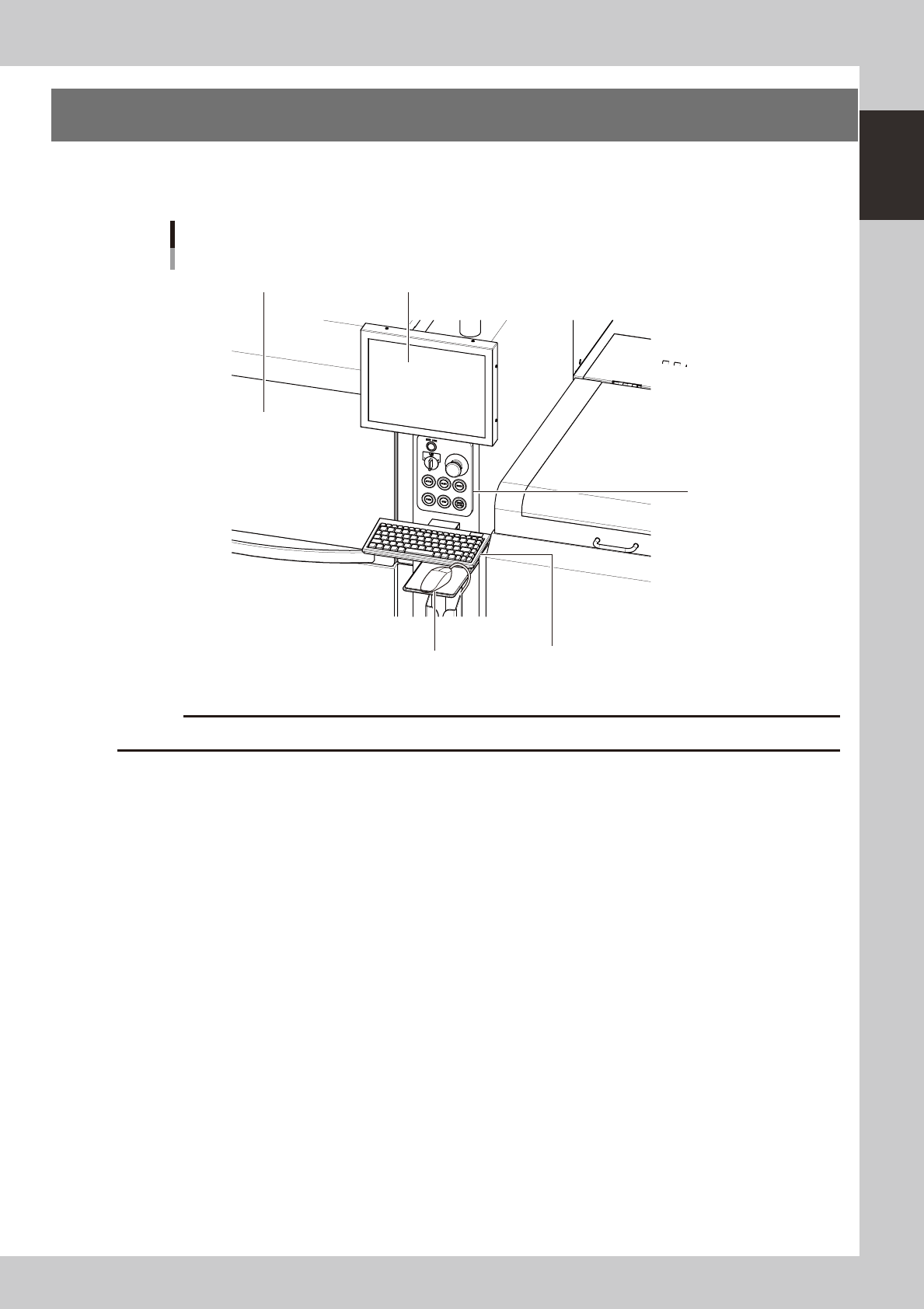
Standard machines are equipped with an operation display, operation panel buttons, a keyboard and a
mouse on the front and rear (option) of the machine, to operate the machine and make data settings.
Front operation panel and keyboard
Upper door (safety cover)
Mouse
Keyboard
Operation display
Operation panel
buttons
63103-N3-00
c
Store the mouse in holder when not in use or it may drop and be damaged.
1-6
1
Part names and functions
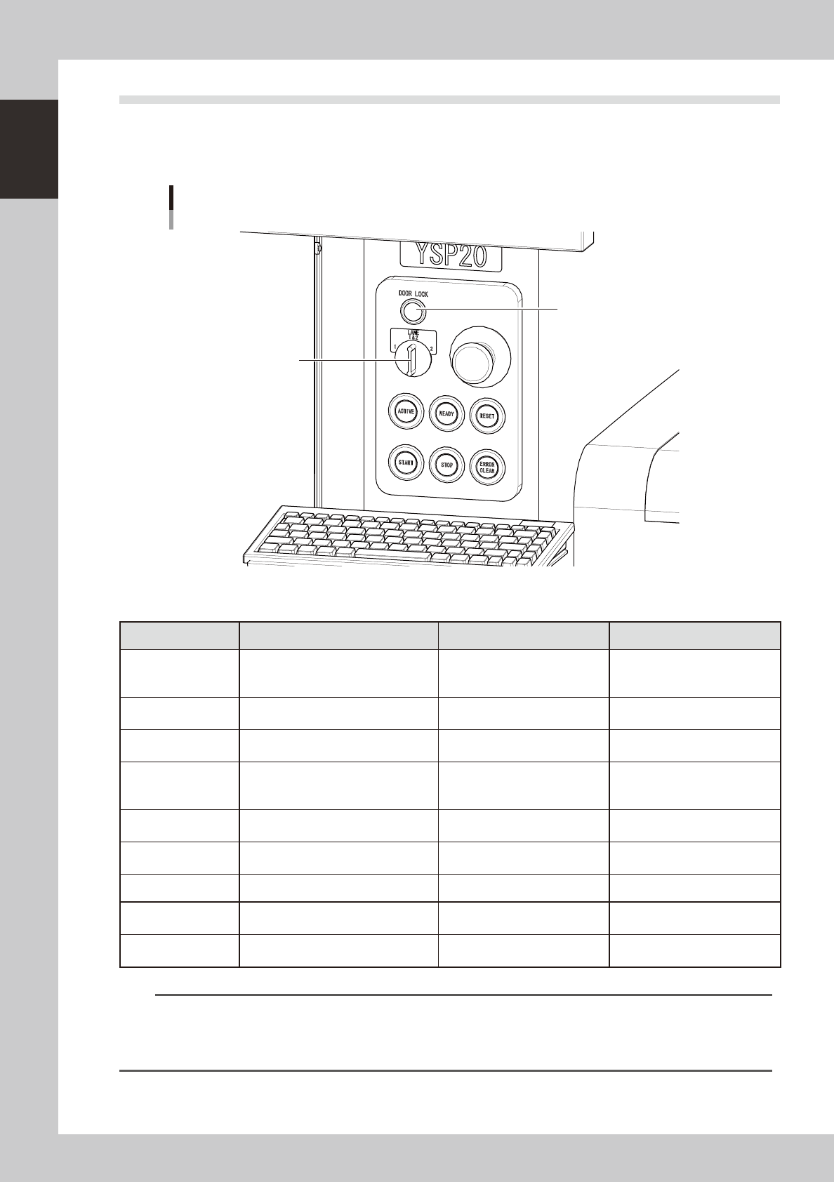
2.1 Operation panel buttons
The operation panel buttons are provided on the front and rear of the machine to run major commands
frequently used to operate the machine. Each button is lit while turned on.
The colors used for the operation
panel are the same as those specified for the signal light (signal tower).
Operation panel buttons
LANE selector switch
DOOR LOCK lamp
63105-N3-00
n
Operation panel button functions
Button name Use the button to: OFF ON
ACTIVE
Enable other keys. (The front and rear
[ACTIVE] keys cannot be turned on
simultaneously.)
• After machine has started.
• The other table has access
rights to operate machine.
• Has access rights to
operate machine.
READY
Release emergency stop and turn the
servo on.
• SERVO OFF
(Motor power OFF)
• SERVO ON
(Motor power ON)
RESET
Stop automatic operation and return to
standby for board production.
• Machine is in normal operation
or stopped.
• Machine has been reset.
START (green)
Perform operation according to board
data.
• Machine is stopped.
• Machine is in normal operation.
[Flash]
Pause or step operation
STOP (Red / White)
Interrupt automatic operation. (Press
START to resume operation.)
• Machine is in normal operation. • Error occurred.
ERROR CLEAR
(Yellow / Blue)
Stop buzzer sound and clear error
screen.
• Machine is in normal operation. • Error occurred.
LANE selector switch Select the lane to control operation.
DOOR LOCK lamp
This lamp indicates whether the door
is locked or unlocked.
• The door is unlocked so you
can open and close it.
• Machine is in normal operation.
EMERGENCY STOP
Trigger emergency stop. Turn to the
right to release it.
n
NOTE
The [ACTIVE] button is provided on both front and rear (option) panels, but cannot be turned on simultaneously. This
means that the [READY], [START], [STOP],[ERROR CLEAR] and [RESET] buttons are enabled only when the [ACTIVE] key
on the same panel is turned on. (The [STOP] button can be used when the [ACTIVE] button is either on or off.)
The keyboard is enabled only when the [ACTIVE] key on the front panel is on.