YSP20_Users_E.pdf - 第58页
1-19 1 Part names and functions 6. Vision camera unit This machine is equipped with a "board vision camera" for recognizing fiducial marks and land patterns on boards; and a "mask vision camera" for r…
1-18
1
Part names and functions
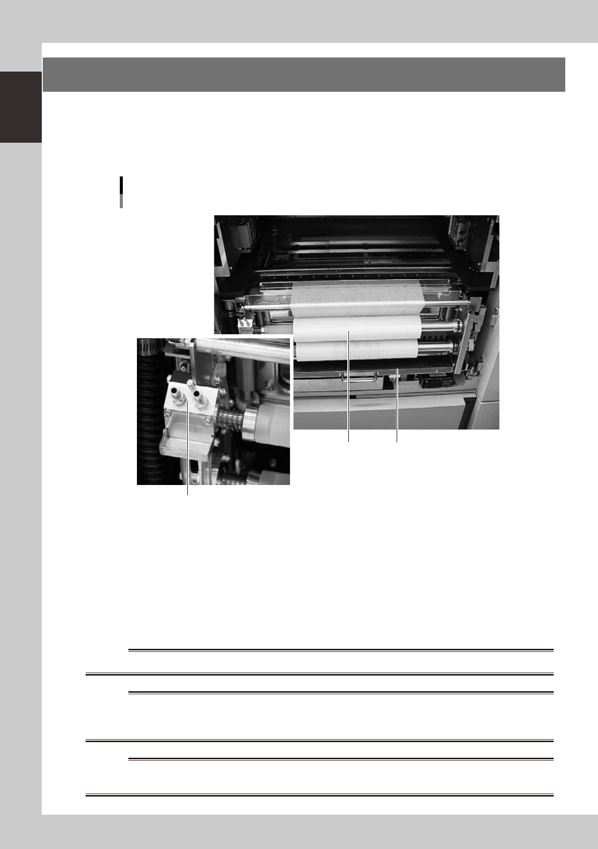
5. Cleaning unit
When you open the machine front and rear panels, there is a cleaning unit under each printing table. The
cleaning unit uses a gauze roll to wipe away solder adhering to the mask apertures and solder coming out of
the backside of the mask while vacuuming. Cleaning can be performed in AUTO mode or MANUAL mode. In
AUTO mode, you can further select wet mode using a solvent (alcohol) or dry mode using the cleaning gauze
only.
Cleaning unit and solvent tank
1 2
3
As viewed from front of RL (right-to-left flow) machine
63121-N3-00
1. Gauze roll
Wipes away solder and flux coming out of the backside of the mask. To replace the used gauze roll see "5. Replacing the
cleaning gauze roll" in Chapter 4.
2. Solvent tank
Lets solvent soak into the cleaning gauze to liquefy remaining solder during the mask cleaning. Insert the nozzle of the
special solvent supply bottle into the solvent refilling joint to refill the tank with solvent.
3. Solvent refilling joint
Insert the nozzle of the special solvent supply bottle into this port.
w
WARNING
w
WARNING
w
WARNING
1-19
1
Part names and functions
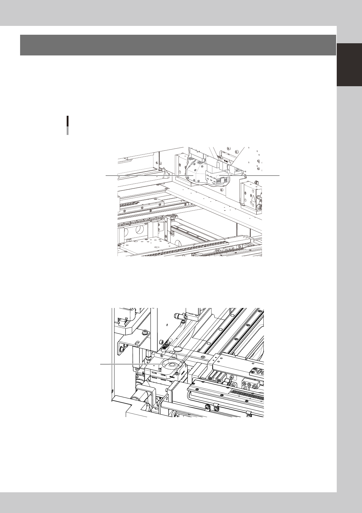
6. Vision camera unit
This machine is equipped with a "board vision camera" for recognizing fiducial marks and land patterns on
boards; and a "mask vision camera" for recognizing fiducial marks on the backside of masks (stencils) and
mask apertures. These cameras are also used as a teaching unit to perform teaching.
A "solder-print inspection camera" is added to machines which have the optional solder-print inspection
function.
These cameras are used as a teaching unit to perform the teaching.
Vision camera unit
1
3
2
N Front right side
N Front left side
As viewed from front of RL (right-to-left flow) machine
63123-N3-00
1. Board vision camera, Lighting unit
This vision camera and lighting unit recognize the surface of a board clamped on the conveyor.
2. Solder-print inspection camera (option), Lighting unit (option)
High-resolution, wide field-of-view camera and lighting unit installed in the YSP with an optional solder-print inspection
function. Refer to the separate "Option manual" for detailed information.
3. Mask vision camera, Lighting unit
This vision camera and lighting unit recognize the backside of a mask (stencil) clamped on the printing table.
1-20
1
Part names and functions
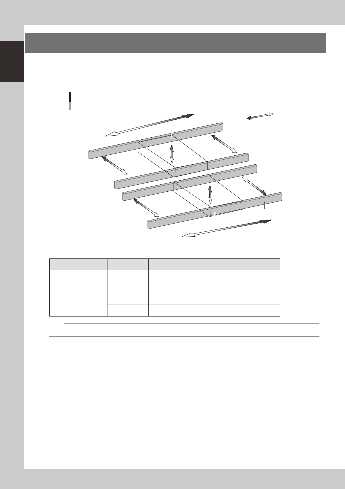
7. Servo-controlled axes
The mechanical units of this machine move along the following servo-controlled axes. Other mechanical
devices are driven by compressed air.
n
Dual-lane
Plus direction
Minus direction
W2-axis
Axis configuration
Lane 1
Lane 2
W1-axis
Y1-axis
Y2-axis
PU1-axis
PU2-axis
X2-axis
X1-axis
Conveyor rail
Board clamp unit (Board clamp table)
Board clamp unit (Board clamp table)
63124-N3-00
n
Axis functions
Unit name Axis Function
Board clamp unit
(Board clamp table)
X1, X2 Moves the board clamp table along the X-axis.
PU1, PU2 Raises and lowers the push-up plate.
Conveyor
Y1, Y2 Moves the conveyor unit along the Y-axis.
W1, W2 Adjusts the conveyor width.
TIP
You can manually move each unit on the operation screen. See "4.1 Move Axis screen" in Chapter 7 for more details.