YSP20_Users_E.pdf - 第51页
1-12 1 Part names and functions 4.2 Board suppor t Backup pins are pro vided to support the board at the printing position by pushing it from the bottom. (Note that board support jigs are optional.) l Backup pins F or ma…
1-11
1
Part names and functions
4. Conveyor unit
The conveyor unit used to clamp a board in mounting position is described below.
n
NOTE
In the case of a dual lane machine, the front is Lane 1 and the rear is Lane 2.
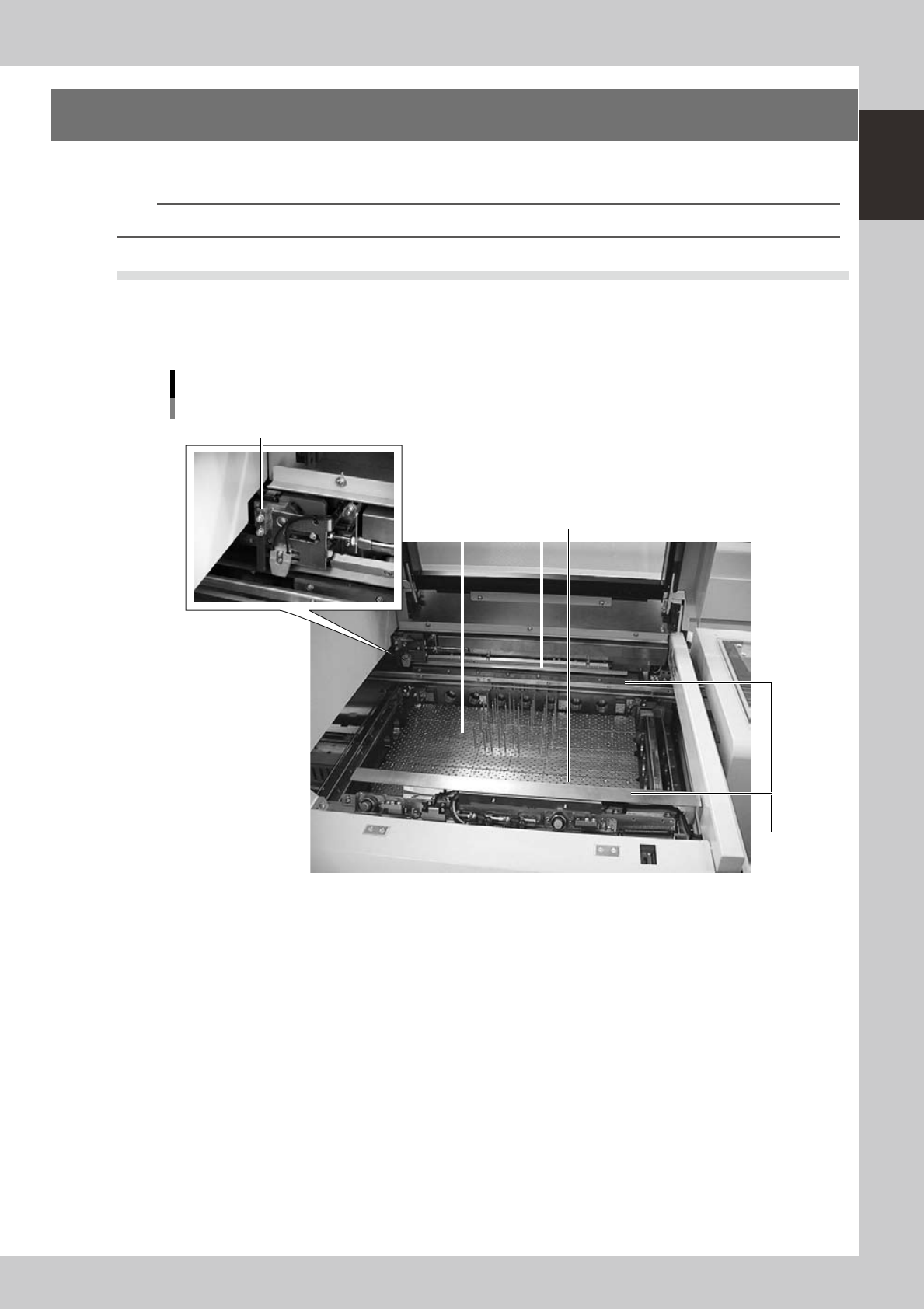
4.1 Board clamp unit (board clamp table)
The board clamp table secures a board in the printing position. During recognition or position teaching by the
vision camera, this table moves along the servo-controlled X and Y axes. The conveyor rail width is
automatically adjusted according to the board width (Board Size Y).
Board clamp unit
board clamp table
2
1
3
4
63113-N3-00
1. Main stopper
When a board is carried in on the conveyor, the main stopper stops the board at the printing position. The main stopper
is automatically positioned by servo control according to the board length (Board Size X).
2. Push-up plate
The push-up plate moves up by servo control to clamp the board from the bottom. This push-up plate has pin insertion
holes arranged in a matrix, into which backup pins can be inserted to support the board. (Board support jigs are
optional.)
3. Flap
Presses on the board edge from the top to correct the board curvature. These flaps are automatically actuated when the
board is clamped in printing position.
4. Edge clamp
Secures the board in printing position by pushing laterally on the board edge.
1-12
1
Part names and functions
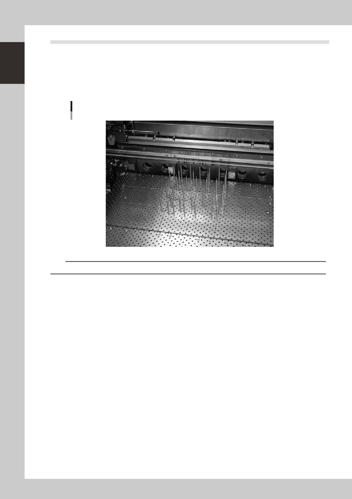
4.2 Board support
Backup pins are provided to support the board at the printing position by pushing it from the bottom. (Note
that board support jigs are optional.)
l
Backup pins
For machines using backup pins, insert the backup pins into the holes in the push-up plate (matrix plate) in positions that
match the board.
Backup pins
Matrix plate
63115-N3-00
TIP
The backup pin arrangement can be registered for each board type. (See "3. Backup pin arrangement" in Chapter 7.)
1-13
1
Part names and functions
l
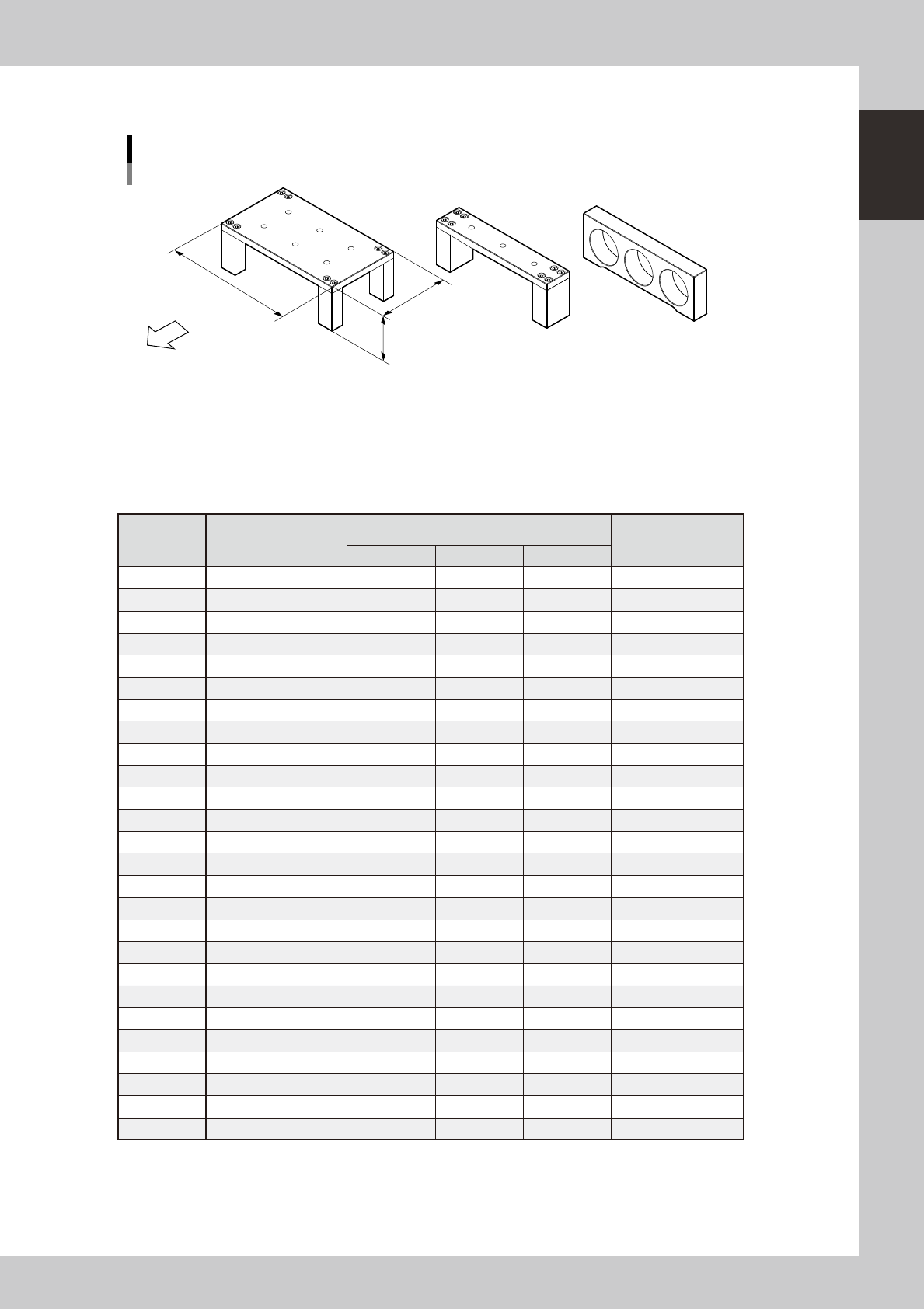
Board support jig combinations
Board support jig dimensions and combination table
Front of machine
(89mm, 15 rows of pin insertion holes) (33mm, 5 rows of pin insertion holes) (19mm, 3 rows of pin insertion holes)
A B C
W
L : 159mm
H : 55mm
63010-N3-00
The table below shows how many A to C blocks are arranged in the W direction and how many pin rows are
used for each board size.
Combine blocks and pins suitable for the board size while referring to the table below.
n
Board support jig combination table
Number of
rows
Applicable board size
(W)
Board support jig type/Q'ty used
Pins combined
(rows)
A B C
5 50 to 52 0 1 0 0
6 52 to 59 0 0 2 0
7 59 to 66 0 0 2 1
8 66 to 73 0 1 1 0
9 73 to 80 0 1 1 1
10 80 to 87 0 2 0 0
11 87 to 94 0 2 0 1
12 94 to 101 0 1 2 1
13 101 to 108 0 2 1 0
14 108 to 115 0 2 1 1
15 115 to 122 1 0 0 0
16 122 to 129 0 2 2 0
17 129 to 136 0 2 2 1
18 136 to 143 1 0 1 0
19 143 to 150 1 0 1 1
20 150 to 157 1 1 0 0
21 157 to 164 1 0 2 0
22 164 to 171 1 0 2 1
23 171 to 178 1 1 1 0
24 178 to 185 1 1 1 1
25 185 to 192 1 1 1 2
26 192 to 199 1 1 2 0
27 199 to 206 1 1 2 1
28 206 to 213 1 2 1 0
29 213 to 220 1 2 1 1
30 220 to 227 2 0 0 0