YSP20_Users_E.pdf - 第52页
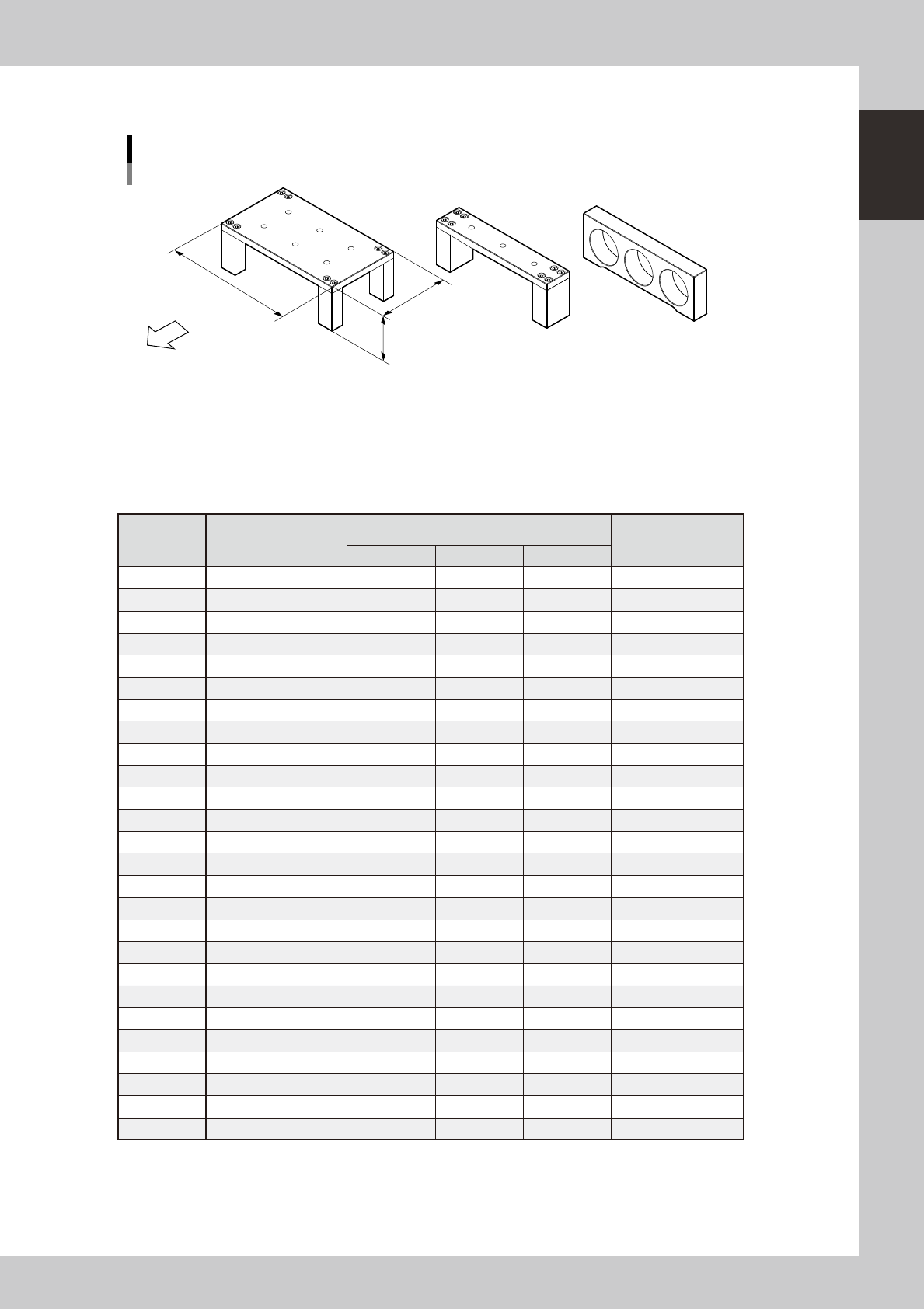
1-13 1 Part names and functions l Board suppor t jig combinations Board support jig dimensions and combination table Front of machine (89mm, 15 rows of pin insertion holes) (33mm, 5 rows of pin insertion holes) (19mm, 3 …
1-12
1
Part names and functions
4.2 Board support
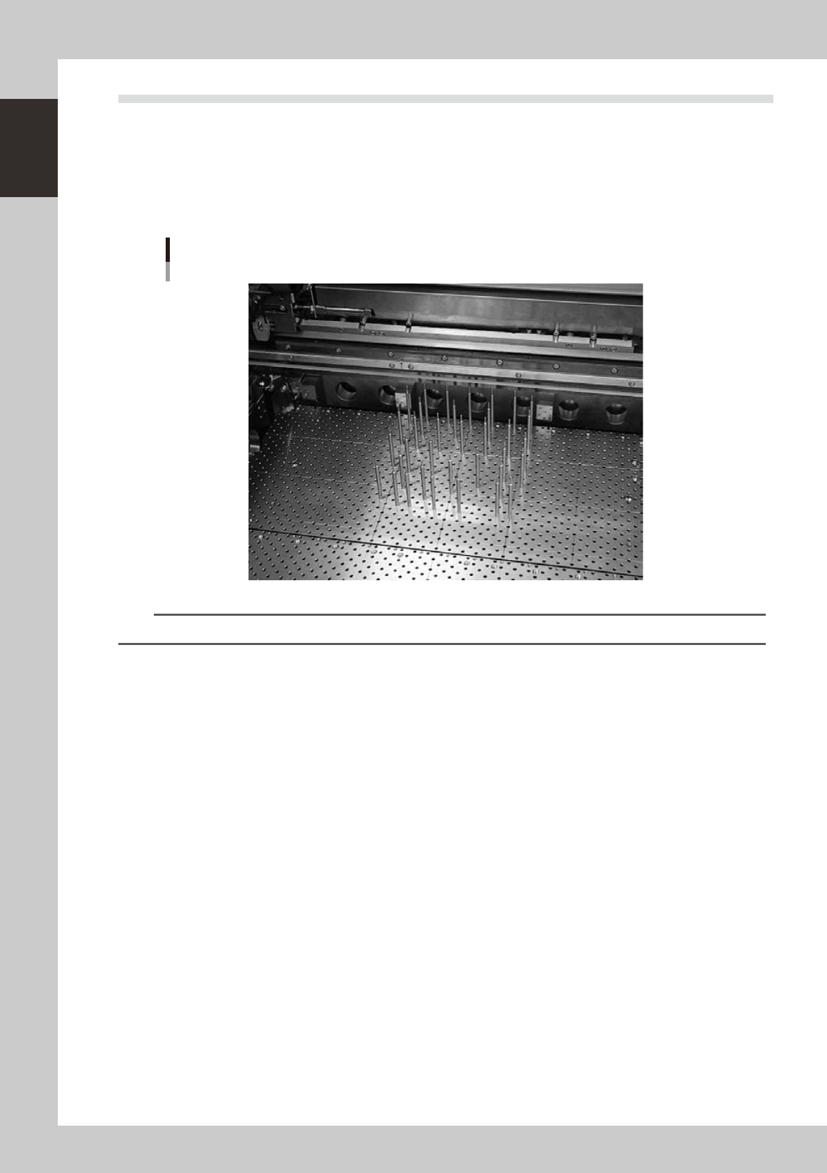
Backup pins are provided to support the board at the printing position by pushing it from the bottom. (Note
that board support jigs are optional.)
l
Backup pins
For machines using backup pins, insert the backup pins into the holes in the push-up plate (matrix plate) in positions that
match the board.
Backup pins
Matrix plate
63115-N3-00
TIP
The backup pin arrangement can be registered for each board type. (See "3. Backup pin arrangement" in Chapter 7.)
1-13
1
Part names and functions
l
Board support jig combinations
Board support jig dimensions and combination table
Front of machine
(89mm, 15 rows of pin insertion holes) (33mm, 5 rows of pin insertion holes) (19mm, 3 rows of pin insertion holes)
A B C
W
L : 159mm
H : 55mm
63010-N3-00
The table below shows how many A to C blocks are arranged in the W direction and how many pin rows are
used for each board size.
Combine blocks and pins suitable for the board size while referring to the table below.
n
Board support jig combination table
Number of
rows
Applicable board size
(W)
Board support jig type/Q'ty used
Pins combined
(rows)
A B C
5 50 to 52 0 1 0 0
6 52 to 59 0 0 2 0
7 59 to 66 0 0 2 1
8 66 to 73 0 1 1 0
9 73 to 80 0 1 1 1
10 80 to 87 0 2 0 0
11 87 to 94 0 2 0 1
12 94 to 101 0 1 2 1
13 101 to 108 0 2 1 0
14 108 to 115 0 2 1 1
15 115 to 122 1 0 0 0
16 122 to 129 0 2 2 0
17 129 to 136 0 2 2 1
18 136 to 143 1 0 1 0
19 143 to 150 1 0 1 1
20 150 to 157 1 1 0 0
21 157 to 164 1 0 2 0
22 164 to 171 1 0 2 1
23 171 to 178 1 1 1 0
24 178 to 185 1 1 1 1
25 185 to 192 1 1 1 2
26 192 to 199 1 1 2 0
27 199 to 206 1 1 2 1
28 206 to 213 1 2 1 0
29 213 to 220 1 2 1 1
30 220 to 227 2 0 0 0
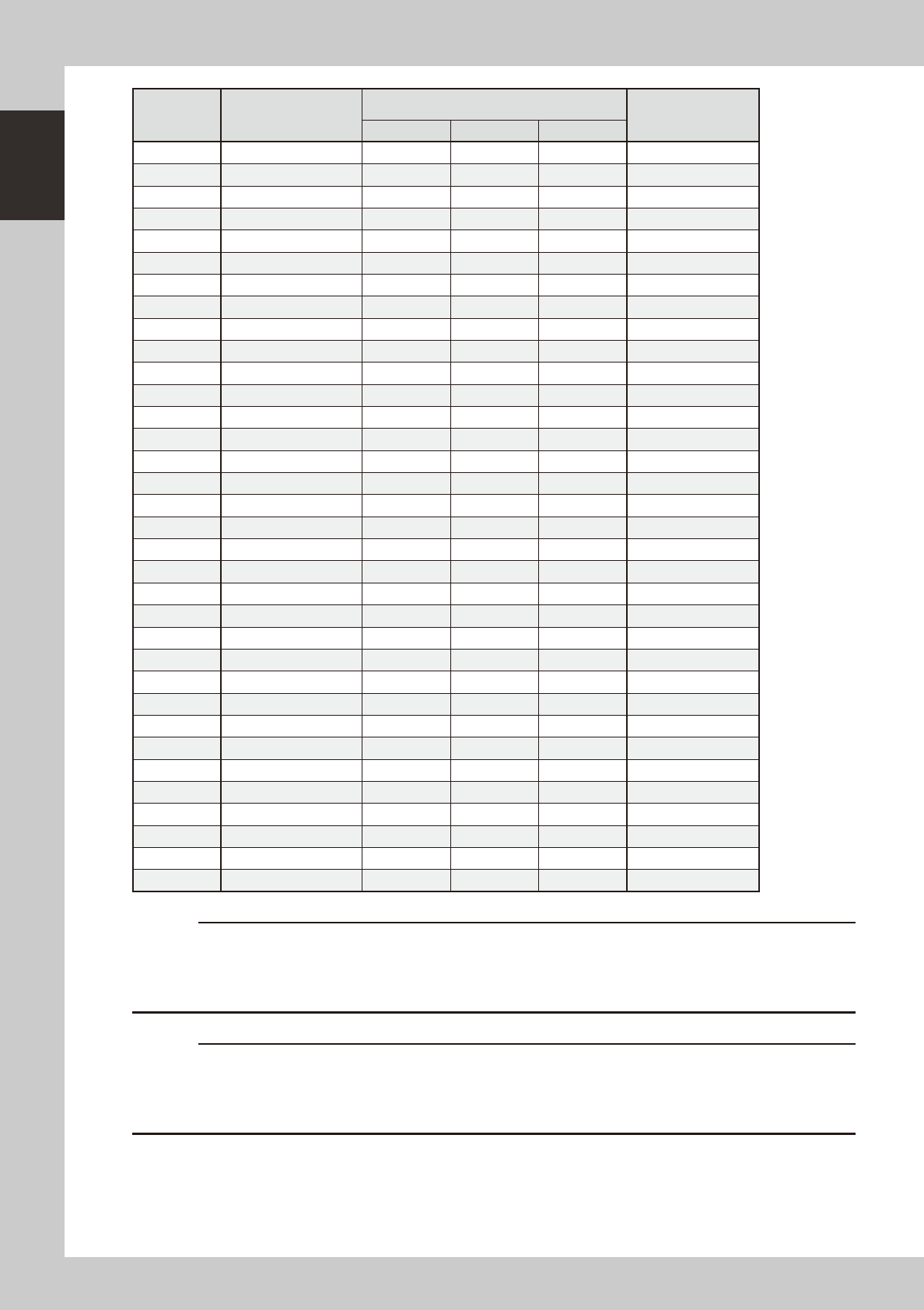
1-14
1
Part names and functions
Number of
rows
Applicable board size
(W)
Board support jig type/Q'ty used
Pins combined
(rows)
A B C
31 227 to 234 1 2 2 0
32 234 to 241 1 2 2 1
33 241 to 248 2 0 1 0
34 248 to 255 2 0 1 1
35 255 to 262 2 1 0 0
36 262 to 269 2 1 0 1
37 269 to 276 2 1 0 2
38 276 to 283 2 1 1 0
39 283 to 290 2 1 1 1
40 290 to 297 2 2 0 0
41 297 to 304 2 2 0 1
42 304 to 311 2 2 0 2
43 311 to 318 2 2 1 0
44 318 to 325 2 2 1 1
45 325 to 332 3 0 0 0
46 332 to 339 3 0 0 1
47 339 to 346 3 0 0 2
48 346 to 353 3 0 1 0
49 353 to 360 3 0 1 1
50 360 to 367 3 1 0 0
51 367 to 374 3 1 0 1
52 374 to 381 3 1 0 2
53 381 to 388 3 1 1 0
54 388 to 395 3 1 1 1
55 395 to 402 3 2 0 0
56 402 to 409 3 2 0 1
57 409 to 416 3 2 0 2
58 416 to 423 3 2 1 0
59 423 to 430 3 2 1 1
60 430 to 437 3 2 1 2
61 437 to 444 3 2 2 0
62 444 to 451 3 2 2 1
63 451 to 458 3 2 2 2
64 458 to 460 3 2 2 3
c
checking that no solder or foreign matter exists on the matrix plate.
machine.
c