YSP20_Users_E.pdf - 第111页
4-19 4 aily operation 7.2 Mask frame dimensions and mask standard position n Mask frame dimensions and mask standard position Recommended specifications Compatible mask frame size (mm) Mask standard position Standard p…
4-18
4
aily operation
7.1 Mask size and mask stopper pin position
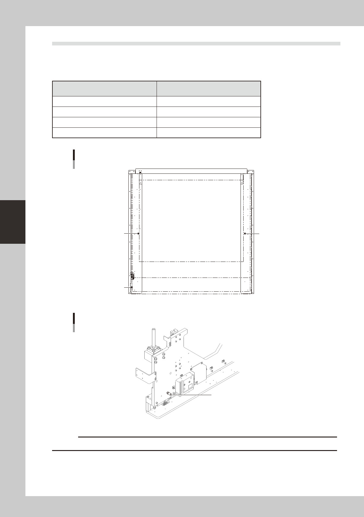
The mask stopper pin position must be changed according to the mask frame size to be used as shown below.
Mask stopper pins are screw types.
n
Mask frame size and stopper pin position
Mask frame size
L (mm) × W (mm)
Mask stopper position
750 × 750 Not used
750 × 650 Not used
736 × 736 1
650 × 550 2&3
Mask size and stopper pin position
1
2
3
63419-N3-00
Mask stopper pin
Mask stopper pin
63420-N3-00
c
Securely tighten the mask stopper pin by hand to prevent it from loosening and falling off.
4-19
4
aily operation
7.2 Mask frame dimensions and mask standard position
n
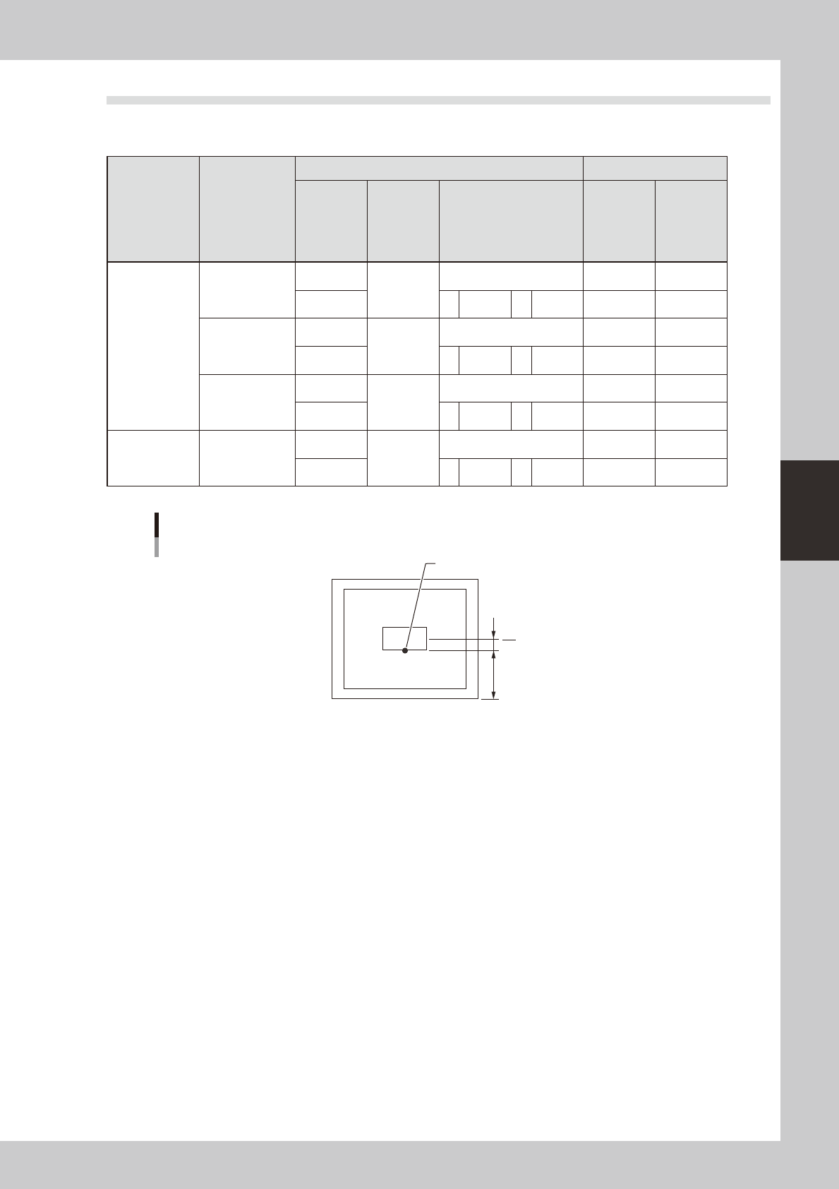
Mask frame dimensions and mask standard position
Recommended
specifications
Compatible
mask frame size
(mm)
Mask standard position Standard position offset
Setting X direction
Y direction
A: From outside of mask
frame (mm)
B: From center of mask
(mm)
X Y
YSP20
recommended
specifications
L750 × W750
Center
Center
Center 0 0
Front A 145 B 230 0 0
L736 × W736
Center
Center
Center 0 0
Front A 138 B 230 0 0
L650 × W550
Center
Center
Center 0 0
Front A 150 B 125 0 0
Minami Kogaku
recommended
specifications
L750 × W650
Center
Center
Center 0 0
Front A 150 B 175 0 0
When mask standard position is “Front”
Mask standard position: “Front”
Mask center
A
B
Standard position
63421-N3-00
4-20
4
aily operation
8. Rolling operation
In rolling operation, the squeegee head moves back and forth repeatedly in order to roll and agitate solder
on the mask until it becomes suitable for printing. Rolling operation is recommended in cases where you first
print after supplying solder on the mask or when solder has been left on the mask for a long time while not in
operation.
n
NOTE
The board surface becomes soiled during rolling operation, so we recommend covering the board surface with a
transparent sheet (available as option). After rolling operation, clean the backside of the mask by automatic or
manual cleaning.
1
Supply solder.
1. Press the [SW Prod. Position] button on the Setup screen.
n
NOTE
When both lanes are used for production, the dialog box for selecting the lane number appears, so select the lane.
The lane currently used in production is grayed out.
2. Select “Solder Setup” and press the [OK] button.
When the DOOR LOCK lamp turns off, open the safety cover and supply solder on the mask.
c
immediately in case of emergency.
2
Press the [READY] button.
Close the safety cover and press the [READY] button.
3
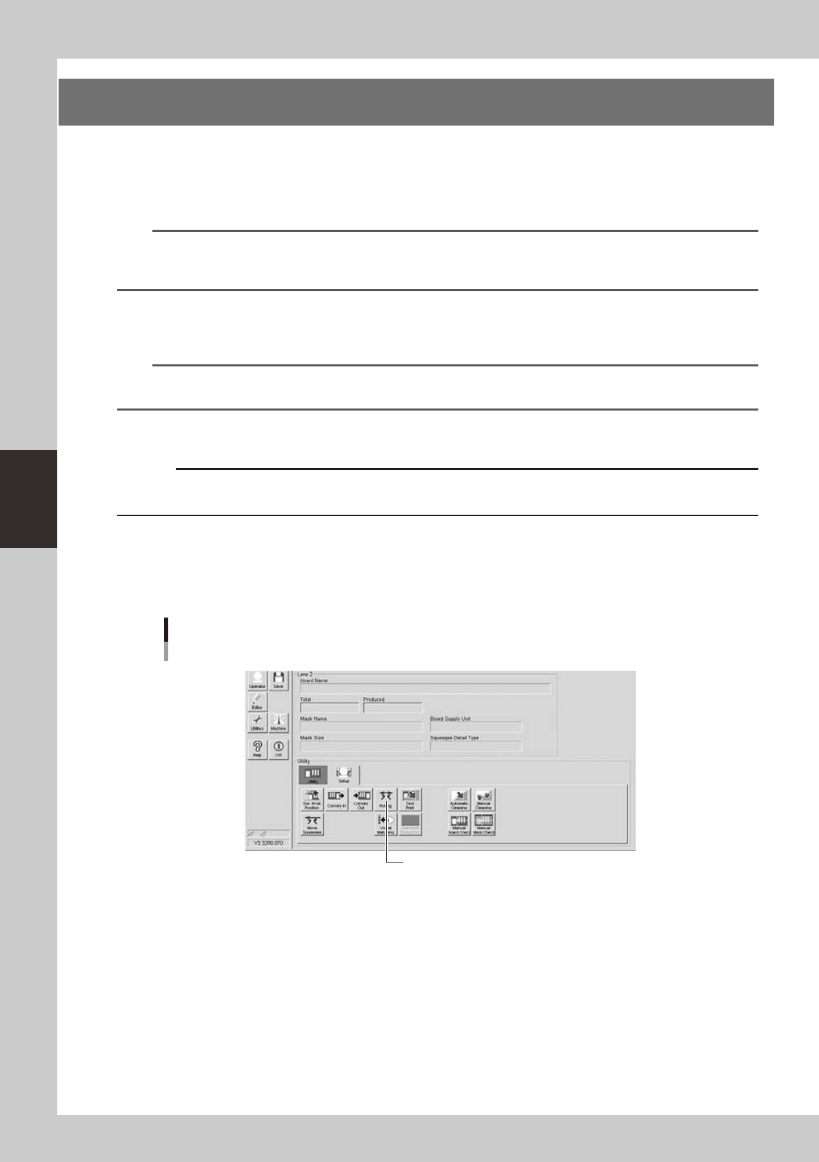
Press the [Rolling] button on the [Setup] tab of the Setup screen.
[Rolling] button
[Rolling] button
64410-N3-10