YSP20_Users_E.pdf - 第146页
5-20 5 Creating and setting the data D: F . & B. Print Condition Select whether to use the same conditions for the forw ard and backward printing. When this parameter is set to "Same Condition", the forward…
5-19
5
Creating and setting the data
5. Squeegee data setting
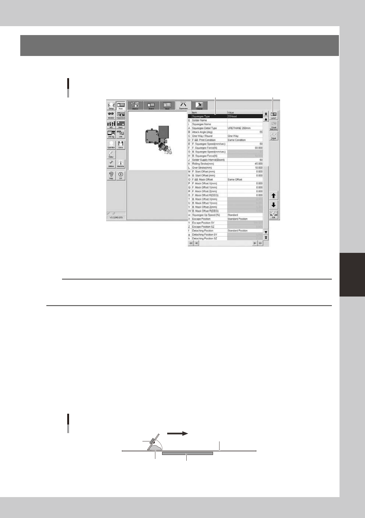
The following parameter items can be checked and edited on the [Print]-[Squeegee] tab.
[Print]-[Squeegee] tab
1 [Lane] button
64522-N3-10
1: Squeegee Type
Select "3S Head” when using the 3S squeegee head. When using an optional double squeegee, select "Double Squeegee".
TIP
The squeegee type has been set in the machine data prior to shipment according to the machine specifications. So
the same squeegee type as set in the machine data must be selected here. If not the same squeegee type, an error
is issued.
E: Solder Name
Enter the name or comment on the solder to be used. You can leave this field blank.
i: Squeeges Name
Enter the name or comment on the squeeges to be used. You can leave this field blank.
A: Squeegee Detail Type
Specify the squeegee type and size when the squeegee type is set to "3S Head” or “Double Squeegee".
B: Attack Angle (deg.)
This parameter is available only when the squeegee type is set to "3S Head". (This parameter does not appear when the
squeegee type is set to "Double Squeegee".)
Set the angle formed between the 3S squeegee scraper and the mask surface in order to print solder most efficiently. The
setting range is from 40 to 65 degrees. (Default setting is 55 degrees.)
Attack angle (3S head only)
Solder
Attack angle (scraper angle)
Board
Mask
3S squeegee scraper
Printing direction
63535-N3-00
C: One Way/Round
Select whether to print solder in one direction or in both directions.
5-20
5
Creating and setting the data
D: F. & B. Print Condition
Select whether to use the same conditions for the forward and backward printing. When this parameter is set to "Same
Condition", the forward and backward printing operations are performed under the conditions specified for the "F.
Squeegee Speed" and "F. Squeegee Force", and the settings for the "B. Squeegee Speed" and "B. Squeegee Force" are
disabled.
E, G: F. Squeegee Speed (mm/sec), B. Squeegee Speed (mm/sec)
Set the forward and backward squeegee movement speeds to print solder. Find an optimum speed while checking the
scraped state of the solder on the mask. If this speed is too fast, the squeegee may not scrape solder properly. If too slow,
solder may spread into the backside of the mask.
F, H: F. Squeegee Force (N), B. Squeegee Force (N)
Set the force (pressure) to apply a load to the squeegee during printing in the forward and backward directions. Check
the scraped state of the solder on the mask to find an optimum squeegee pressure. Set this pressure at a lower pressure as
long as the solder is scraped properly. A larger squeegee pressure is required as the squeegee speed is set faster.
J: Solder Supply Interval (Board)
Set the number of boards to be printed per one supply of solder, based on the amounts of solder supplied and used
during printing.
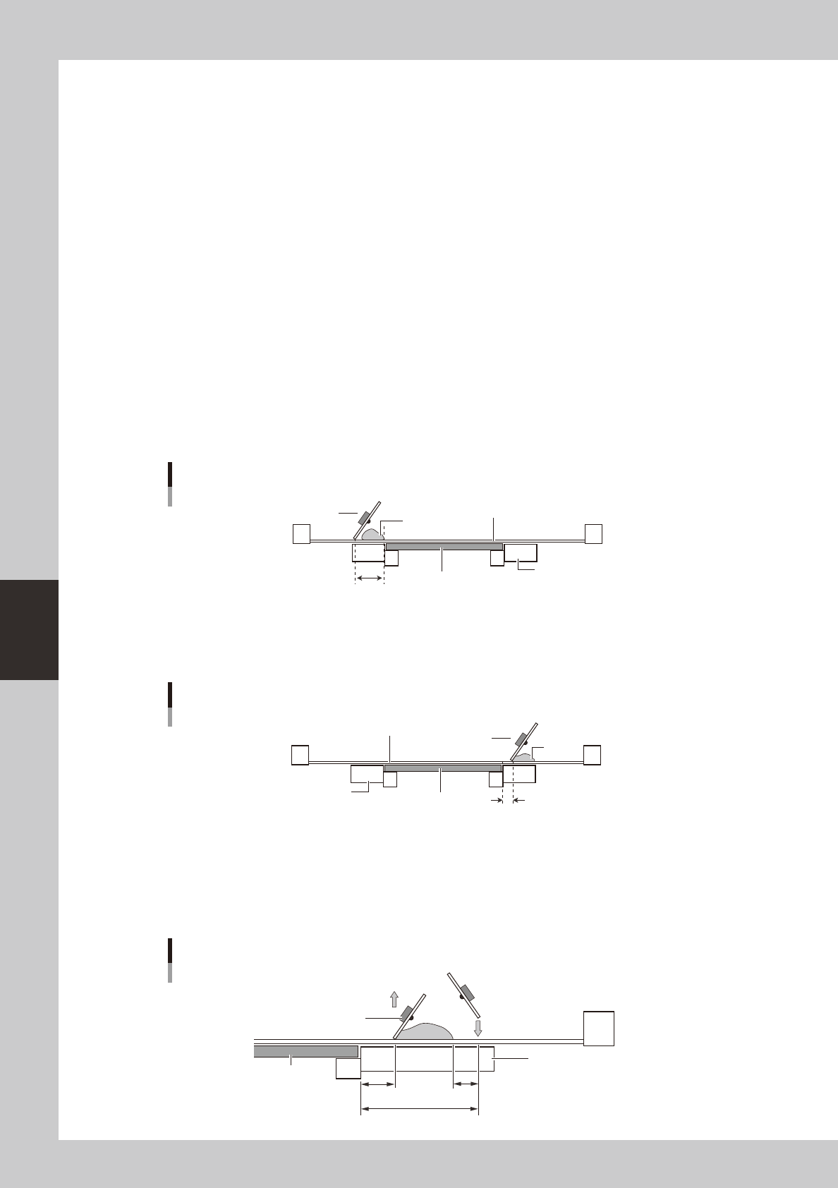
K: Rolling Stroke (mm)
Specify the distance (millimeters) from the position at which the squeegee lands on the mask to the edge of the board.
Usually set to 40 to 45mm.
Rolling stroke
Squeegee
Solder
Mask surface
Conveyor
Board
Rolling stroke
63514-N3-00
L: Over Stroke (mm)
Specify the distance (millimeters) from the other edge of the board to the position at which the squeegee takes off the
mask after printing solder. Usually set to 5 to 10mm.
Over stroke
Solder
Board
Conveyor
Mask surface
Over stroke
Squeegee
63515-N3-00
l
Relation between rolling stroke and over stroke
If the rolling stroke is set vary small and the over stroke is set very large, the squeegee will land onto the solder. Set the
rolling stroke to a distance of "over-stroke + solder width + margin (+
α
)" as
shown below. If the sum of the rolling stroke
and over stroke distances exceeds 50mm, the squeegee goes away from the conveyor, and so the printing pressure may
become abnormal.
Relation between rolling stroke and over stroke
+A
Board
Conveyor
Rolling stroke
Squeegee
Over stroke
Squeegee moves
down at rolling
stroke start position.
63527-N3-00
5-21
5
Creating and setting the data
M: F. Start Offset (Forward movement start offset)
This parameter sets how far to print (or that amount of offset) inwards on the board from the closer edge of the board (or
lower edge in drawing below).
N: B. Start Offset (Backward movement start offset)
This parameter sets how far to print (or that amount of offset) inwards on the board from the farther edge of the board (or
upper edge in drawing below).
n
NOTE
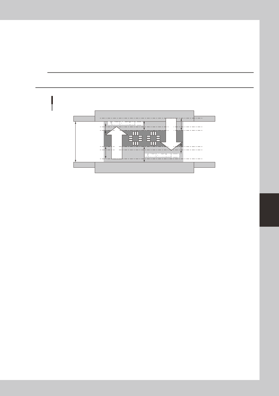
The print range of the squeegee is basically a reference position determined by the “Start Offset" and “Start Offset”
parameters. You can use this print range to set the “Rolling Stroke” and “Over Stroke” parameters.
Squeegee print range
Board size Y=130 (mm)
Over Stroke=10 (mm)
B. Start Offset=30 (mm)
F. Start Offset=50 (mm)
B. Start Offset=30 (mm)
F. Start Offset=50 (mm)
Rolling Stroke=40 (mm)
Rolling Stroke=40 (mm)
Over Stroke=10 (mm)
Forward printing
Return printing
Forward printing
Return printing
63516-N3-00
As shown in the drawing above, let's consider cases where you print in the dark shaded area 50 mm from the closer edge
(lower edge in drawing) and 30 mm from the farther side of a board whose Y size is 130mm.
When the rolling stroke is made 40 mm and the "Over Stroke" 10 mm as a distance for good solder paste uniformity, the
print movement range of the squeegee during forward and return printing is the section shown by the arrows in the
drawing. The parameter settings will then be as follows.
Rolling Stroke (mm) 40.000
Over Stroke (mm) 10.000
S. Start Offset (mm) 50.000
B. Start Offset (mm) 30.000
O: F. & B. Mask Offset
Select whether to apply the same manual alignment offset for the forward and backward printing. When this parameter is
set to "Same Offset", the forward and backward printing operations are performed under the conditions specified for the
"F. Mask Offset X, Y, Z, R", and the settings for the "B. Mask Offset X, Y, Z, R " are disabled.
P: F. Mask Offset X (mm)
When printing in the forward direction (from the front side to the inner side), the mask surface may stretch in the
advancing direction, causing an X-direction shift versus the land patterns. To correct this positional shift, enter an offset
value here.
If shifted in the plus direction : Enter a plus offset value.
If shifted in the minus direction : Enter a minus offset value.
Q: F. Mask Offset Y (mm)
When printing in the forward direction (from the front side to the inner side), the mask surface may stretch in the
advancing direction, causing a Y-direction shift versus the land patterns. To correct this positional shift, enter an offset
value here.
If shifted in the plus direction : Enter a plus offset value.
If shifted in the minus direction : Enter a minus offset value.
R: F. Mask Offset Z (mm)
When printing in the forward direction (from the front side to the inner side), the mask surface may stretch in the Z
direction. Enter this offset here. Leave this parameter set to "0.000" in most cases.