YSP20_Users_E.pdf - 第78页
Chapter 3 Printing guide T his chapter explains data setting and changeover tasks to perform satisfactory solder printing. This c hapter also describes the relation between the print trouble symptoms and the conditions t…
2-16
2
asic operations
3.2 Various buttons and parameter input grids
Various types of buttons, selection tabs and parameter input grids are used on the operation screen.
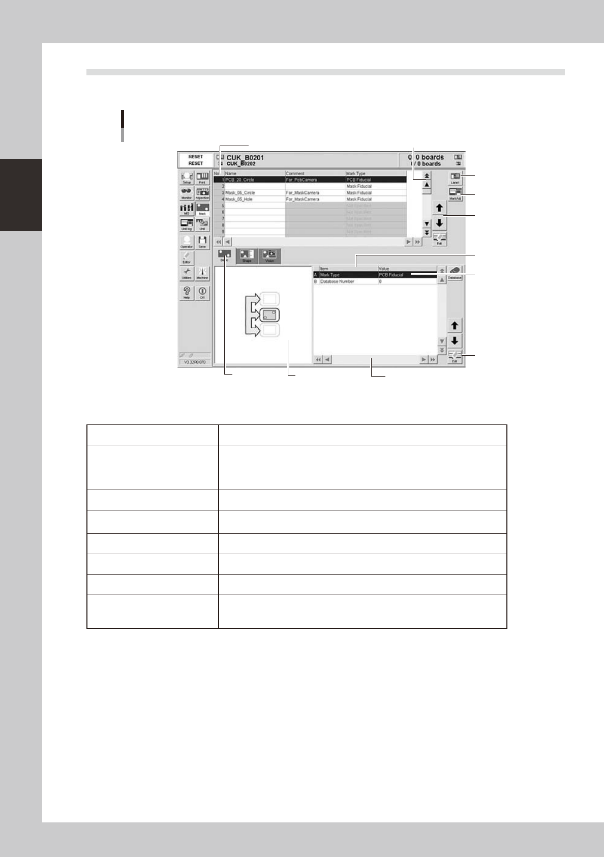
Operation screen basic elements
Mark screen
Line up/down
button
Vertical scroll bar & button
Edit button
Operation
button
Lane
button
Horizontal scroll bar & button
Assistant
screen
Selection
tab
Parameter
list
Parameter
input box
Data No. list
64209-N3-10
n
Buttons and basic elements on operation screen
Selection tab Select this tab to switch the parameter input screen.
Parameter input box
Select, enter or edit parameters here. When the keyboard is used, double-click
on a parameter input box to enter or edit the data.
When a touch screen (option) is used, press the [Edit] button on the lower right
of the parameter list. The edit box then pops up for data input and editing.
Scroll bar and button Use the scroll bars or arrow buttons to see hidden items in the parameter list.
Lane button
Use this button to change dual-lane board data.
This button is not displayed when single-lane board data is selected.
Operation button Press these buttons to open the next operation screen or dialog box.
Cursor up/down button Use these buttons to move the cursor up or down through the parameter list.
Edit button Press this button to open the edit dialog box for the selected parameter item.
Assistance screen
Shows an illustration or information useful for parameter input or editing.
Alphabet characters shown in the parameter list and in the illustration on this
screen correspond to each other.

Chapter 3 Printing guide
This chapter explains data setting and changeover tasks to perform satisfactory solder printing. This chapter also describes the
relation between the print trouble symptoms and the conditions that may cause the trouble.
Before starting operation described in Chapter 4, “Daily operation”, read this chapter carefully.
Contents
1
2
2
2.2 Alignment offset setting 3-4
2.3 Rolling 3-5
2.4 Printing and production conditions 3-6
7
7
3.1.1 Edge clamp pressure 3-7
3.1.2 Backup jig 3-7
8
3.3 Alignment offset 3-8
3.4 Squeegee (Rolling) 3-9
3.4.1 Squeegee speed 3-9
3.4.2 Squeegee pressure 3-9
3.4.3 Attack angle (degree (°)) 3-9
3.5 Solder supply interval 3-10
0
3.6.1 Board separation speed 3-10
3.6.2 Board separation distance 3-11
3.7 Cleaning 3-11
3.7.1 Cleaning interval 3-11
3.7.2 Cleaning repeat 3-11
3.7.3 Cleaning speed 3-11
4.
Causes of troubles predicted from symptoms (Appendix)
3-12
4.1 Positional deviation 3-12
2
4.3 Insufficient filling 3-12
3
4.5 Scraping trouble 3-13
4.6 Solder enlargement 3-13
3
3-1
3
Printing guide
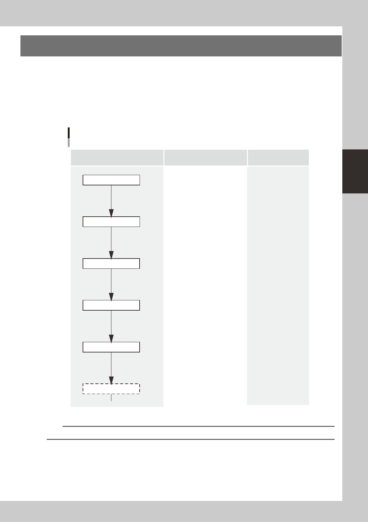
1. Flow of printing condition setting
The following diagram shows the flow of the condition setting (data setting) and the setup work necessary to
perform the printing with excellent quality.
•
Before starting the condition setting, it is necessary that the basic data input and the setup work have been completed.
•
The parameter change results after completion of the condition setting may slightly vary depending on the solder and/
or mask status.
•
It is recommended to first perform the test print with the default values and gradually narrow the conditions from the
test print results.
Printing condition setting
Contents of work Items to be set Related troubles
Setup work
Basic data input
・Alignment offsets X, Y, R
・Board size
・Mask information
・Squeegee type
・Edge clamp pressure
・Fiducial position coordinates
・Backup jig setting
・Board clamp status check
・Mark information check
Print deviation
Solder spread
Solder bridge
Print deviation
Solder enlargement
Solder chipping, mask remaining
Solder spread, solder bridge
Blur
Scraping trouble
Insufficient filling
・Squeegee pressure
・Squeegee speed
・Attack angle
・Board separation speed
・Board separation distance
・Alignment offset Z
・Solder supply interval
Solder chipping, mask remaining
Solder spread, solder bridge
・Cleaning interval
・Cleaning repeat
・Cleaning speed
Alignment offset
Cleaning conditions
Printed status check
Graphic alignment
Test print
Rolling
63300-N3-00
n
NOTE
For more details about work procedures and contents of each parameter, see the relevant sections in this chapter.