YSP20_Users_E.pdf - 第86页
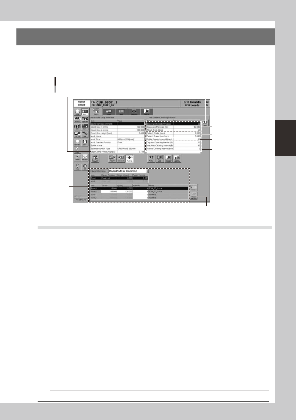
3-8 3 Printing guide 3.2 Board and mask mark recognition (Mark position) n Function T hese parameters set coordinates of the fiducial mark positions of the board and mask. The camer a moves to the mark position to recogn…
3-7
3
Printing guide
3. Details of each parameter item
To continuously perform the production with excellent printing quality, it is absolutely required to properly set
conditions for each solder paste printer as described previously.
The following describes how the conditions for each operation affect the printing quality.
Each parameter item
3.1.1 Edge clamp pressure
3.2. Board and mask mark recognition 3.3 Alignment offset
3.4 Squeegee
3.6 Detach pattern
3.7.1
Cleaning interval
3.5
Solder supply interval
[Lane] button
64304-N3-00
3.1 Board clamp
3.1.1 Edge clamp pressure
n
Function
This parameter sets a level of the air pressure supplied to the cylinder which is used to catch a board and clamp it.
n
Setting range and initial value
This parameter can be set in a range of 0.05 to 0.225MPa.
The initial value is 0.225MPa.
n
Setting procedures
Set a pressure level so that the board does not move and become deformed.
As you set a desired pressure level on the program, the regulator automatically adjusts the edge clamp pressure level.
3.1.2 Backup jig
n
Function
This jig supports a board from the bottom when it is clamped.
n
Setting procedures
There are three kinds of backup jigs as described below.
• Backup pin : Used with the push-up pins inserted into the matrix plate. (Printing of B-surface of double
sided mounted board, etc.)
• Flat surface backup : Used with the blocks (support jigs) placed on the matrix plate. (Mounted board with one
flat side)
• Vacuum gripper
backup : Used for boards having a height of 0.5mm or less. (This backup is set on the [Board] tab
screen.)
n
NOTE
Backup pins and flat surface backup can be used together to support a board.
3-8
3
Printing guide
3.2 Board and mask mark recognition (Mark position)
n
Function
These parameters set coordinates of the fiducial mark positions of the board and mask. The camera moves to the mark
position to recognize the fiducial mark so as to align the board and mark positions.
n
Setting procedures
Enter accurate coordinates based on the CAD data of the board and mask.
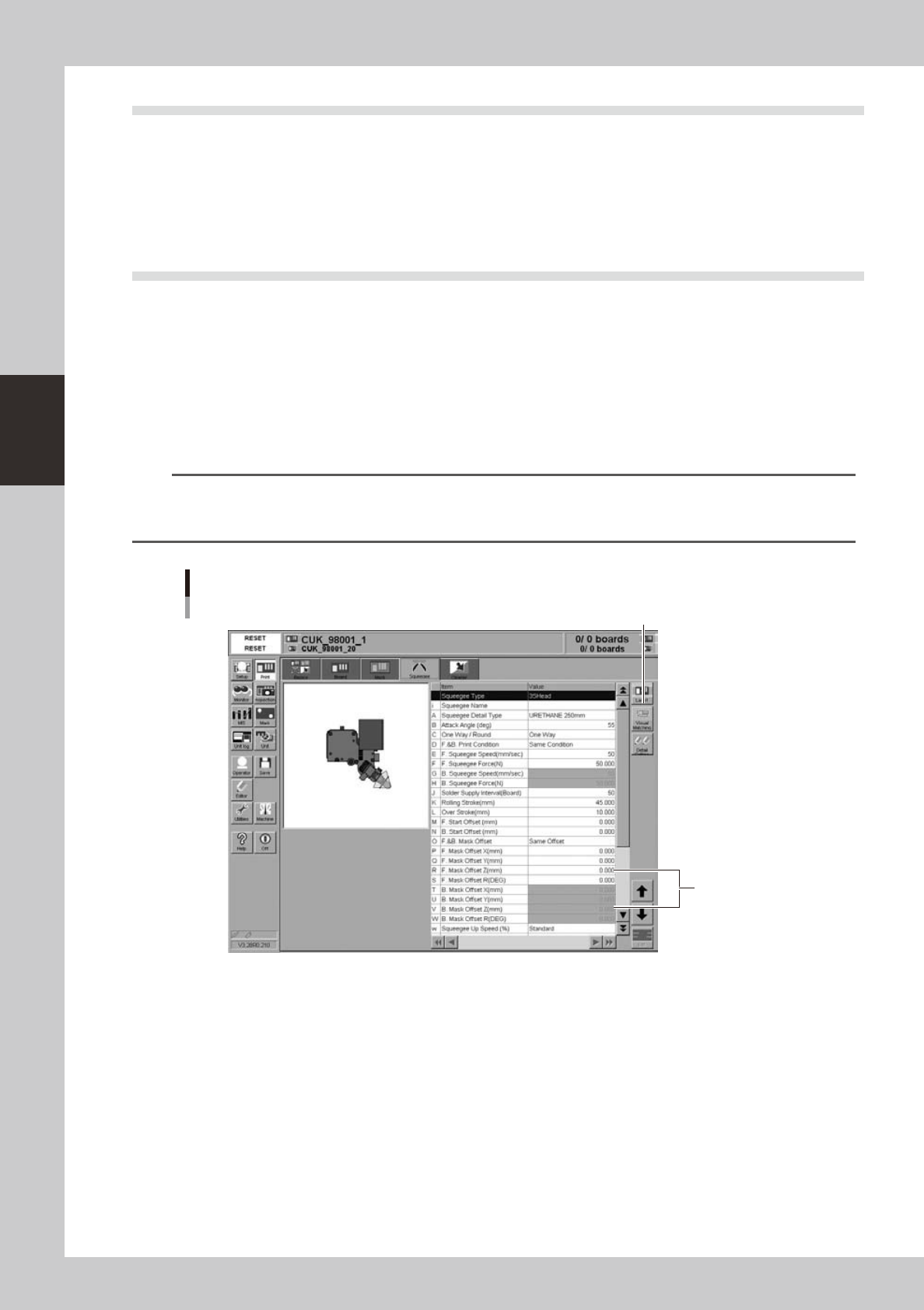
3.3 Alignment offset
n
Function
Normally, the board and mask mark positions are set with the CAD data. Therefore, as each mark is recognized, the
board pattern is aligned with the mask apertures precisely. However, if any deviation, such as elongation of board
occurs, these offset values are used to correct this deviation.
n
Setting procedures
Offset values can be set in the X, Y, Z, and R directions.
To set offset values in the X, Y, and R directions, press the [Visual Matching] button on the [Basics] tab screen to set them.
n
NOTE
You cannot set the offset values in the Z direction with the graphic alignment. Check the contact status between the
mask and board during the rolling test. Enter appropriate values in the [Mask Offset Z] fields on the [Squeegee] tab
screen directly.
Alignment offset Z
Enter values
in these fields.
[Lane] button
64305-N3-00
3-9
3
Printing guide
3.4 Squeegee (Rolling)
3.4.1 Squeegee speed
n
Function
This parameter sets a squeegee movement speed.
n
Setting range and initial value
This parameter can be set in a range of 1 to 200mm/sec.
The initial value is 50mm/sec.
n
Setting procedures
Set a speed at which the solder does not slip on the mask while carefully checking the rolling status.
If the solder scraping on the mask is insufficient, decrease the speed.
3.4.2 Squeegee pressure
n
Function
This parameter sets a squeegee pressure level.
n
Setting range and initial value
This parameter can be set in a range of 1 to 200N.
The initial value is 50 N.
n
Setting procedures
Set this parameter corresponding to the solder scraping status on the mask.
Particularly, for the urethane squeegee, if the squeegee pressure level is too high, the solder is scraped away too much,
causing the filling volume to decrease. If the squeegee pressure level is too low, a scraping trouble occurs in both the
urethane and metal squeegees, resulting in an excessive solder trouble or a missing solder trouble.
n
NOTE
Use both "Squeegee speed" and "Squeegee pressure" to adjust the solder scraping.
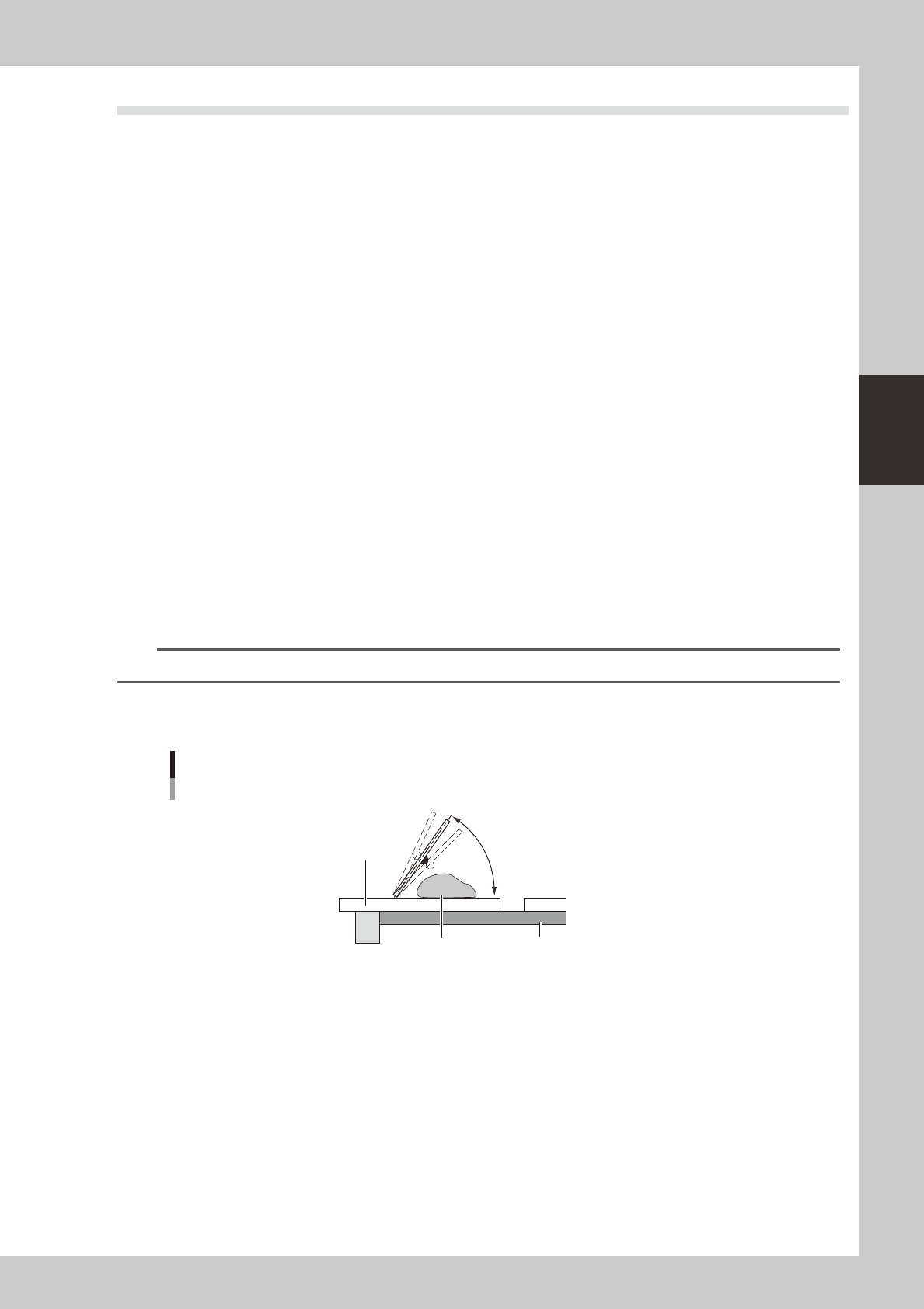
3.4.3 Attack angle (degree (°))
Attack angle
Solder
Attack angle
Board
Mask
55° (Default)
63301-N3-00
n
Function
This parameter sets an attack angle (angle between the squeegee and mask).
n
Setting range and initial value
This parameter can be set in a range of 45 to 65°.
The initial value is 55°.
n
Setting procedures
Increasing the angle will decrease the solder filling volume. Conversely, decreasing the angle will increase the solder
filling volume.