YSP20_Users_E.pdf - 第46页
1-7 1 Part names and functions 2.2 Keyboard and mouse T his machine is equipped with a keyboard and mouse as standard features to operate the machine or for data editing. T o select a menu button or parameter item on the…
1-6
1
Part names and functions
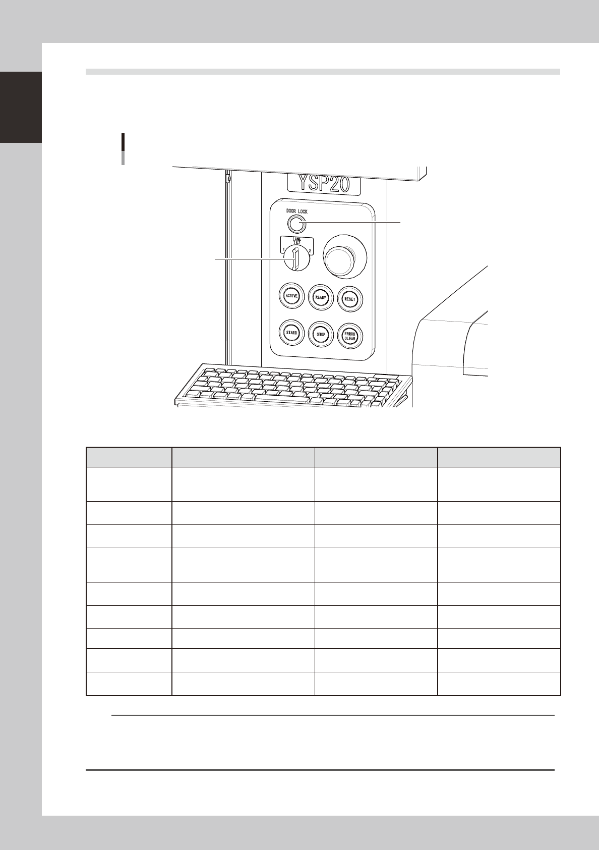
2.1 Operation panel buttons
The operation panel buttons are provided on the front and rear of the machine to run major commands
frequently used to operate the machine. Each button is lit while turned on.
The colors used for the operation
panel are the same as those specified for the signal light (signal tower).
Operation panel buttons
LANE selector switch
DOOR LOCK lamp
63105-N3-00
n
Operation panel button functions
Button name Use the button to: OFF ON
ACTIVE
Enable other keys. (The front and rear
[ACTIVE] keys cannot be turned on
simultaneously.)
• After machine has started.
• The other table has access
rights to operate machine.
• Has access rights to
operate machine.
READY
Release emergency stop and turn the
servo on.
• SERVO OFF
(Motor power OFF)
• SERVO ON
(Motor power ON)
RESET
Stop automatic operation and return to
standby for board production.
• Machine is in normal operation
or stopped.
• Machine has been reset.
START (green)
Perform operation according to board
data.
• Machine is stopped.
• Machine is in normal operation.
[Flash]
Pause or step operation
STOP (Red / White)
Interrupt automatic operation. (Press
START to resume operation.)
• Machine is in normal operation. • Error occurred.
ERROR CLEAR
(Yellow / Blue)
Stop buzzer sound and clear error
screen.
• Machine is in normal operation. • Error occurred.
LANE selector switch Select the lane to control operation.
DOOR LOCK lamp
This lamp indicates whether the door
is locked or unlocked.
• The door is unlocked so you
can open and close it.
• Machine is in normal operation.
EMERGENCY STOP
Trigger emergency stop. Turn to the
right to release it.
n
NOTE
The [ACTIVE] button is provided on both front and rear (option) panels, but cannot be turned on simultaneously. This
means that the [READY], [START], [STOP],[ERROR CLEAR] and [RESET] buttons are enabled only when the [ACTIVE] key
on the same panel is turned on. (The [STOP] button can be used when the [ACTIVE] button is either on or off.)
The keyboard is enabled only when the [ACTIVE] key on the front panel is on.
1-7
1
Part names and functions
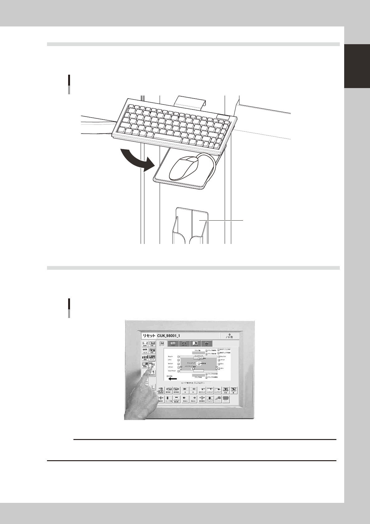
2.2 Keyboard and mouse
This machine is equipped with a keyboard and mouse as standard features to operate the machine or for data
editing. To select a menu button or parameter item on the operation screen, click it with the left mouse button.
Keyboard and mouse
Mouse holder
63107-N3-00
2.3 Liquid crystal touch screen (option)
Machines equipped with a touch screen (option) can be operated or data set by pressing icon buttons or
selecting parameter items on the screen without having to use the keyboard and mouse.
Touch screen
Option
63108-N3-00
c
1-8
1
Part names and functions
3. Printing section
This machine uses a printing pressure feedback head, highly-rigid dual stage, and dual mask (stencil) table
to print solder paste at high speeds yet with high accuracy.
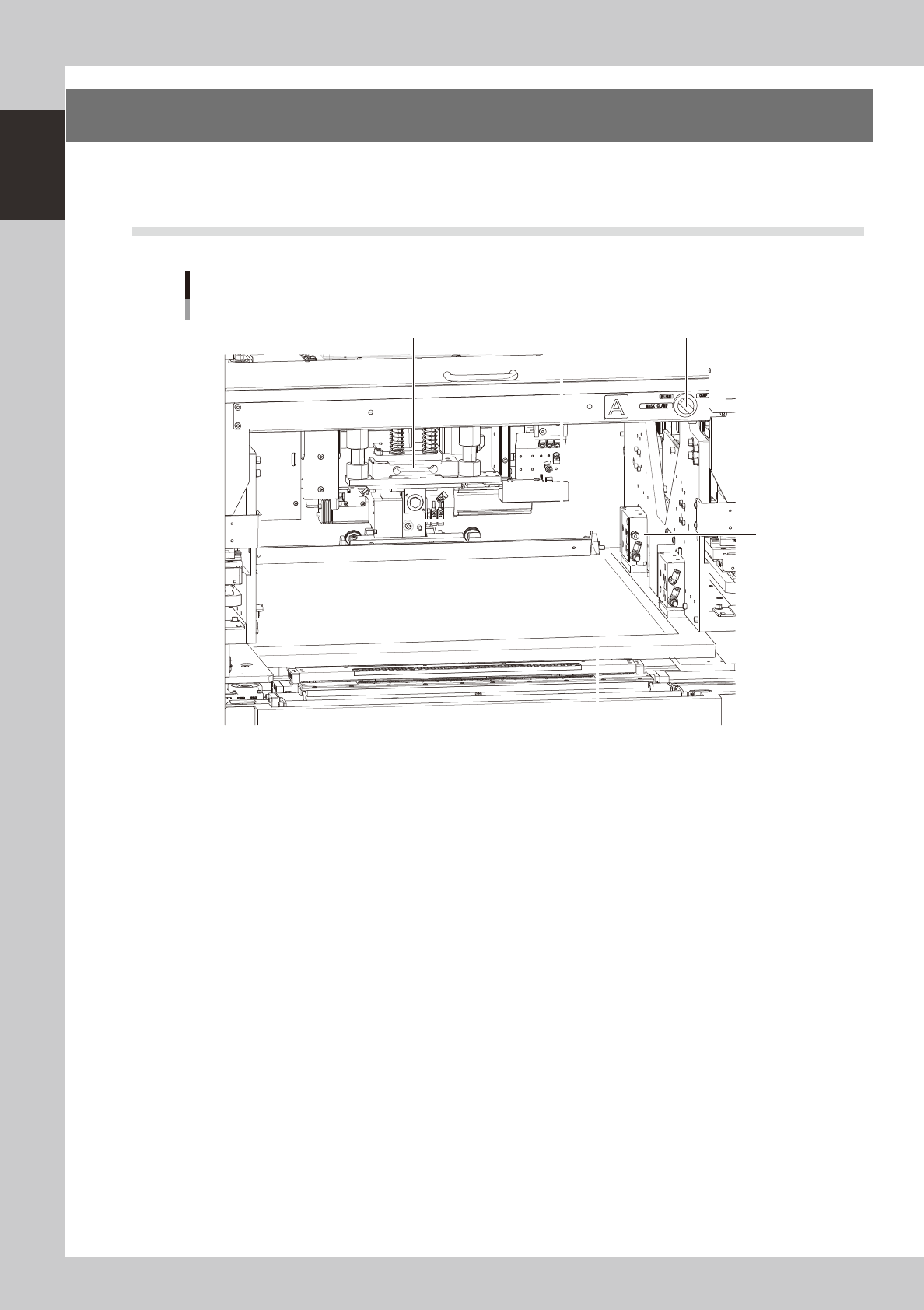
3.1 Squeegee head and printing table
Squeegee head and printing table
1 2 4
3
5
63109-N3-00
1. Squeegee head
Moves the squeegee vertically (along the SZ-axis) and forwards or backwards (along the SY-axis ). The 3S squeegee head
rotates slightly even in the R direction.
2. Squeegee holder
The squeegee can be easily mounted in this squeegee holder with two screws.
3. Mask clamps (a total of 8 clamps)
Clamp a mask (stencil) frame on the printing table. There are 4 clamps on each table (a total of 8 clamps).
4. Mask clamp switch
Turn this switch CCW or CW to release or clamp the mask.
5. Mask (prepared by user)
Various types of masks (stencils) with different frame sizes can be used by just changing the position of the stopper pin.
For information about the mask frame sizes and stopper pin positions, See "7.1. Mask size and mask stopper pin position"
in Chapter 4.