YSP20_Users_E.pdf - 第260页
2-16 2 Inspection and maintenance 6 Insert a new blo wer hose into place. 1. Insert the new blower hose and pass it through the hose clamps. n NOTE Insert the blower hose so that it smoothly bends upward. 2. Connect the …
2-15
2
Inspection and maintenance
q
Take out the filter and clean it.
Take out the ring filter and blow the air from
the inside of the filter with an air blow tool.
If there are heavy dust deposits in the filter,
replace it with a new filter.
w
Return the filter to its original
position.
Fit the filter into place and then reattach the
cover.
3.3.2 Replacing the blower hose
To replace the blower hose, follow the steps below.
n
Required tools
• Slotted screwdriver
• Hex wrench (4mm)
• Replacement blower hose (KKX-M3674-0XX TUBE 25)
e
1
Press the emergency stop button.
2
Release the Y-axis brakes on both
lanes.
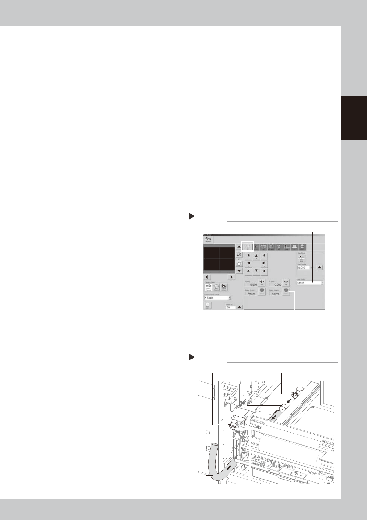
1. On the [Unit]-[Conveyor] tab, press the
[Axis] to open the “Move Axis” screen.
2. Open the [XY] tab and select “Lane 1”
from the “Select Lane” drop-down list.
3. Press the [Brake] button for the Y-axis to
release the brake.
4. Select “Lane 2” and press the [Brake]
button to release the Y-axis brake on
Lane 2.
54201-N3-00
3
Open the safety cover and front
panel of the machine.
Open the safety cover and front panel on
the lane where you will replace the blower
hose.
4
Remove the blower hose from the
cleaner.
1. Move the unit on the Y-axis to the inner
end of the machine.
2. Loosen the hose band with a flat-blade
screwdriver and remove the blower hose
from the joint.
5
Remove the blower hose from the
blower.
1. Loosen the hose band with a flat-blade
screwdriver and remove the blower hose
from the joint.
2. Loosen the mounting bolts on the hose
clamps (2 bolts on each clamp) with an
Allen wrench (4mm).
3. Pull out the blower hose.
53211-N3-00
[Move Axis] screen
Step 2
Select “Lane”.
Y-axis [Brake] button
Removing the blower hose
Step 4,5
Hose bandHose band Hose clamp
Joint
Vacuum pipe
Blower hose
2-16
2
Inspection and maintenance
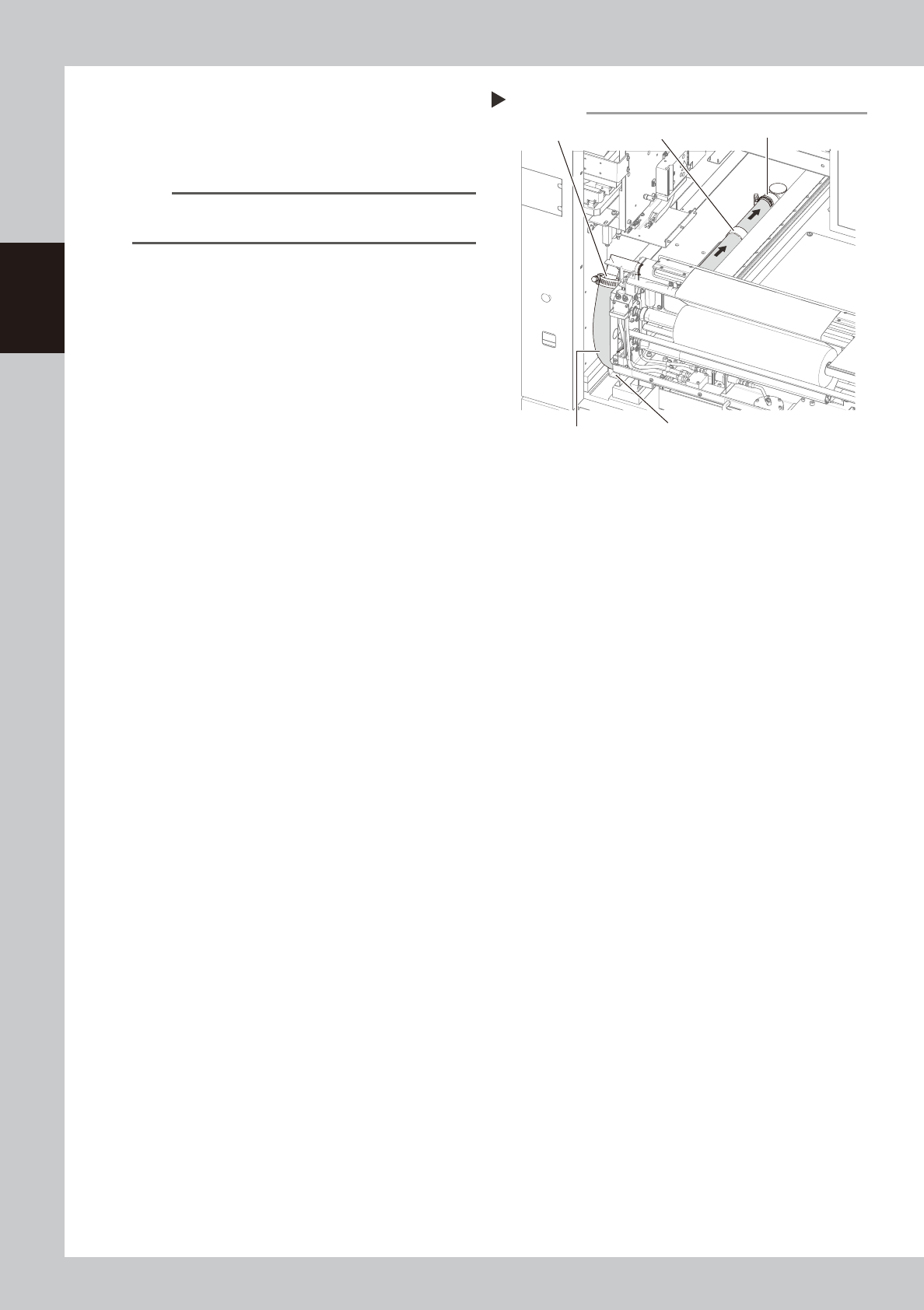
6
Insert a new blower hose into
place.
1. Insert the new blower hose and pass it
through the hose clamps.
n
NOTE
Insert the blower hose so that it smoothly bends
upward.
2. Connect the blower hose to the joint and
tighten the hose band with the flat-blade
screwdriver to clamp the hose.
3. Temporarily connect the blower hose to
the vacuum pipe.
53212-N3-00
7
Check the blower hose position.
Make sure the blower hose is placed straight
in the hose guide.
8
Clamp the blower hose.
1. Using the flat-blade screwdriver, tighten
the hose band on the vacuum pipe to
clamp the hose.
2. Using the Allen wrench (4mm), tighten
the mounting bolts on the hose clamps (2
bolts on each clamp) to clamp the
blower hose.
9
Close the safety cover and front
panel of the machine.
Inserting the blower hose
Step 6
Hose guide
Blower hose
Vacuum pipe
Hose clampJoint
2-17
2
Inspection and maintenance
3.4 Cleaning/replacing filter for mask vacuum chuck
To clean or replace the filter for the vacuum chuck which is used to hold a mask (stencil), the conveyor should
be moved to the setup position on the X-axis.
The following steps describe the procedure for cleaning or replacing the filter on Lane 1.
n
Required tools
• Replacement filter (KGJ-M9140-B0X SPARE FILTER)
• Air blow tool (option)
1
Load board data.
Select any board data and load it.
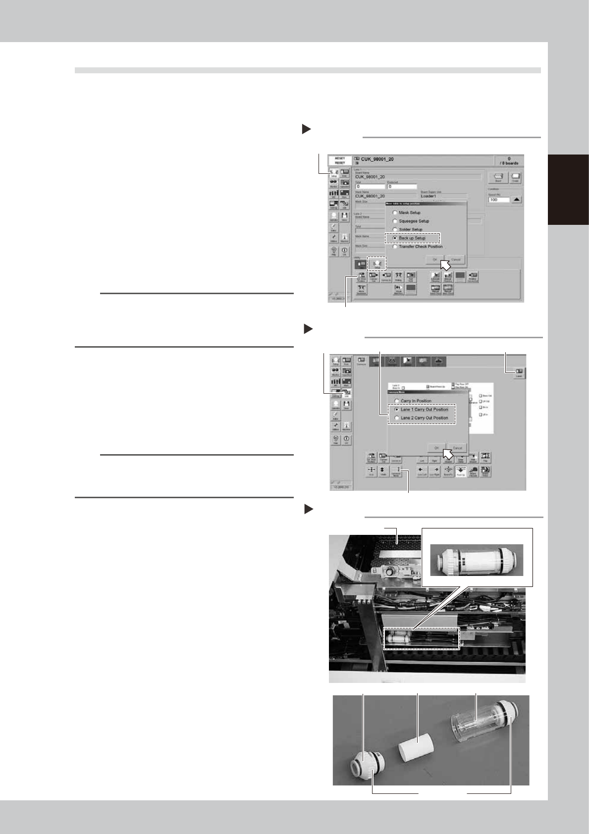
2
Open the [Setup]-[Setup] tab and
press the [SW Prod. Position]
button.
The “Move table to setup position” dialog
box appears. Select “Backup Setup” and
press the [OK] button.
54202-N3-00
TIP
When board data is selected for both lanes, pressing
the [SW Prod. Position] button opens the dialog box for
selecting the lane number, so select the lane where
you will clean or replace the filter.
3
Open the [Setup]-[Conveyor] tab
and press the [Conveyor Move]
button.
The “Move conveyor” dialog box appears,
so select the lane to move the conveyor to
the setup position and press the [OK] button.
The conveyor on the selected lane then
moves to the setup position on the X-axis.
TIP
When board data is selected on both lanes, select the
lane with the [Lane] button and then press the
[Conveyor Move] button.
54203-N3-00
4
Open the setup cover.
5
Remove the filter unit.
Remove the filter unit from the air hose by
turning the left and right joint caps on the
filter unit.
53213-N3-00
6
Take the filter out of the filter unit.
Turn the joint cap, which has marks L (Lock)
and O (Open) on it, to the “O” direction and
take the filter out of the transparent case.
7
Clean the filter.
Use the air blow tool to blow away dust and
impurities trapped in the filter, by blowing air
from the inside and also from the outside. If
the filter is excessively dirty and cannot be
cleaned, replace it with a new filter.
8
Reattach the filter unit.
1. Put the filter into the transparent case
and tighten the removed joint cap by
turning it to the “L” direction.
2. Reattach the filter unit.
“Conveyor Move” dialog box
Step 3
[Unit] button [Lane] buttonSelect the lane.
[Conveyor Move] button
Filter unit
Step 5,6
Backup unit
joint cap
Filter Transparent case
Filter unit
L and O marks
“Move table to setup position” dialog box
Step 2
[Setup] button
[SW Prod. Position] button