YSP20_Users_E.pdf - 第56页
1-17 1 Part names and functions T he YTC (option) is installed next to the YSP20 as shown below . As with the YSP20, the front conveyor r ails on the YTC are called Lane 1, and the rear conveyor r ails Lane 2. In both la…
1-16
1
Part names and functions
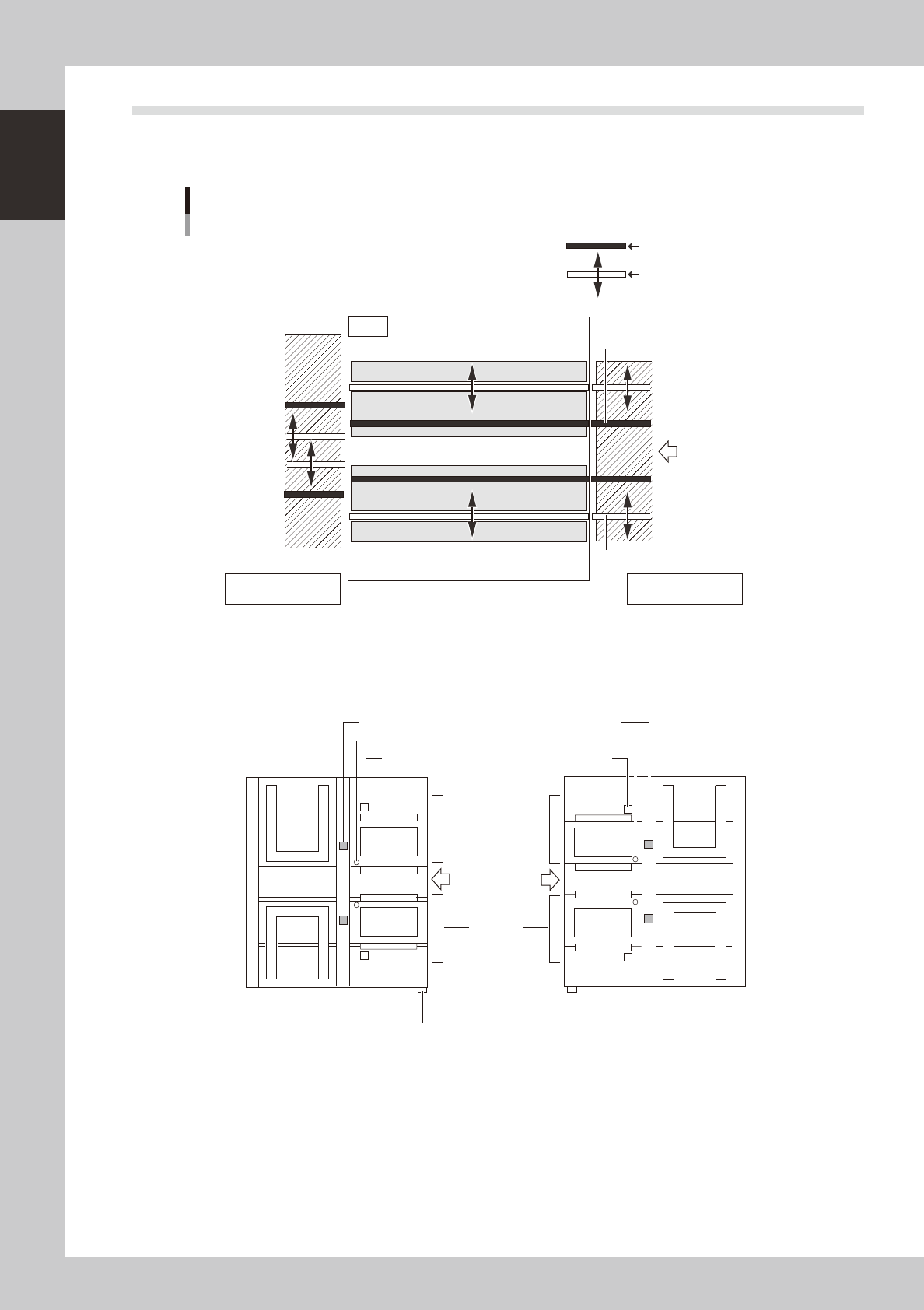
4.4 Conveyor layout
The conveyor rails of this machine are arranged as shown below. In Lane 1 and Lane 2, the inner rail is fixed
and the outer rail is movable.
Conveyor layout
Lane 2
Downstream machine
(YAMAHA dual line model)
Fixed conveyor rail
Movable conveyor rail
Direction of board flow
Lane 1
Does not move when conveyor
width is adjusted.
Moves when conveyor width is
adjusted.
Upstream machine
(two loaders)
Direction of
board flow
NRight-to-left flow NLeft-to-right flow
Mask stage
B-table
Mask stage
B-table
Mask stage
A-table
Mask stage
A-table
Board camera Board camera
Main stopper
Main stopper
Mask camera Mask camera
Main switch
Push-up plate
Push-up plate
Push-up plate
Push-up plate
Lane 1
Lane 2
Main switch
YSP20
63126-N3-00
1-17
1
Part names and functions
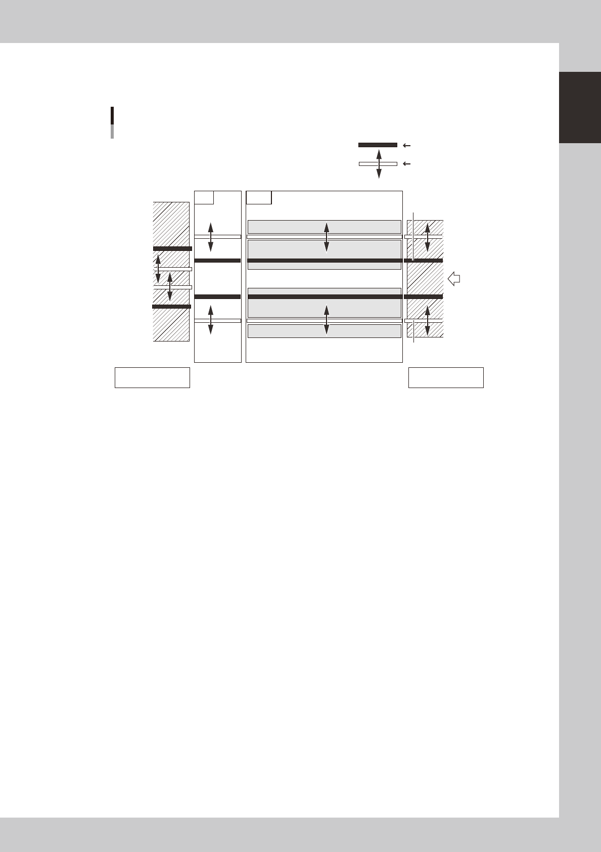
The YTC (option) is installed next to the YSP20 as shown below.
As with the YSP20, the front conveyor rails on the YTC are called Lane 1, and the rear conveyor rails Lane 2. In
both lanes, the inner rail is fixed and the outer rail is movable to adjust the conveyor width.
Conveyor layout
When the machine has a YTC (option)
Lane 2
Fixed conveyor rail
Movable conveyor rail
Direction of
board flow
Lane 1
YSP20YTC
Does not move when conveyor
width is adjusted.
Moves when conveyor width is
adjusted.
Downstream machine
(YAMAHA dual line model)
Upstream machine
(two loaders)
63129-N3-00
1-18
1
Part names and functions
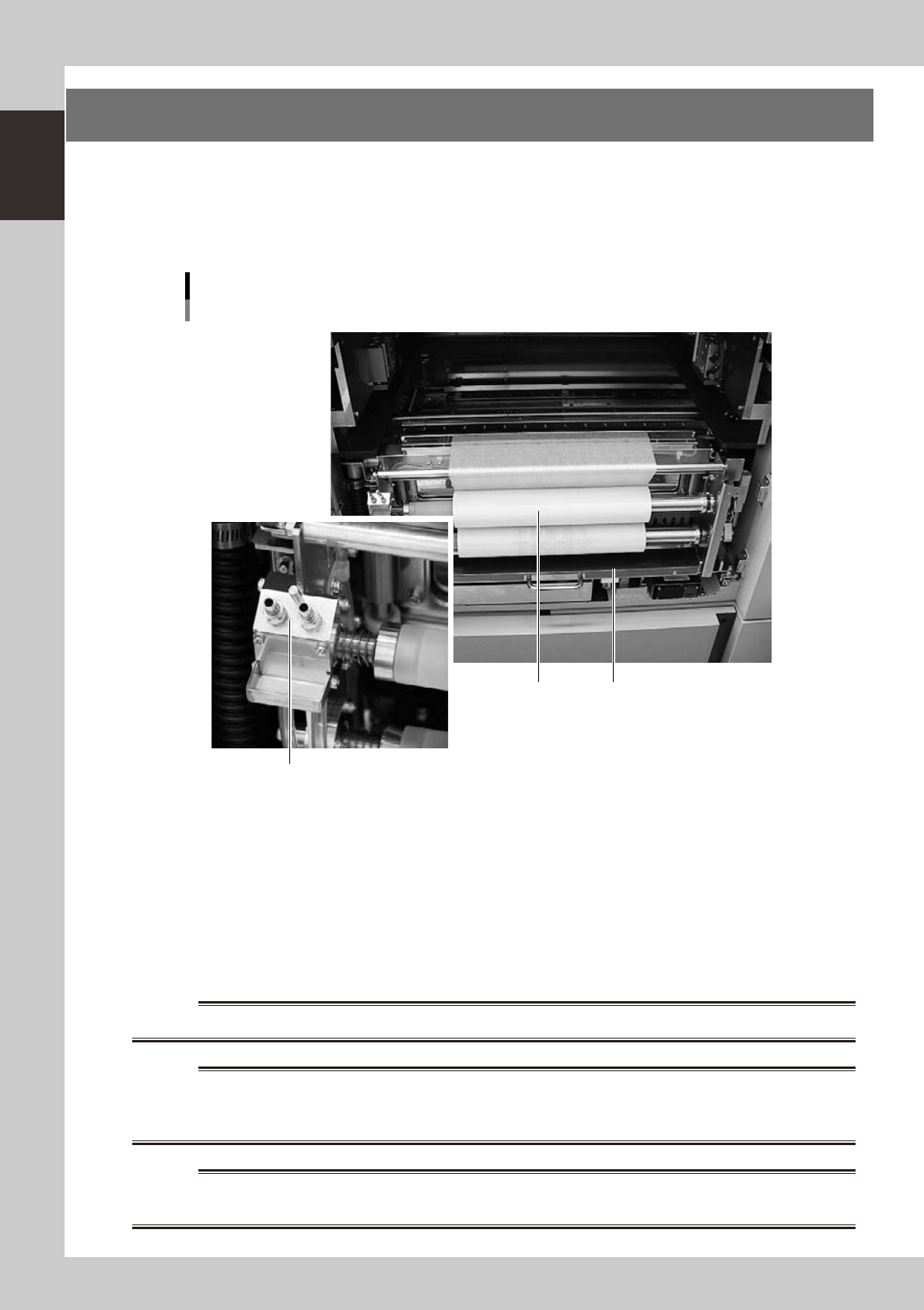
5. Cleaning unit
When you open the machine front and rear panels, there is a cleaning unit under each printing table. The
cleaning unit uses a gauze roll to wipe away solder adhering to the mask apertures and solder coming out of
the backside of the mask while vacuuming. Cleaning can be performed in AUTO mode or MANUAL mode. In
AUTO mode, you can further select wet mode using a solvent (alcohol) or dry mode using the cleaning gauze
only.
Cleaning unit and solvent tank
1 2
3
As viewed from front of RL (right-to-left flow) machine
63121-N3-00
1. Gauze roll
Wipes away solder and flux coming out of the backside of the mask. To replace the used gauze roll see "5. Replacing the
cleaning gauze roll" in Chapter 4.
2. Solvent tank
Lets solvent soak into the cleaning gauze to liquefy remaining solder during the mask cleaning. Insert the nozzle of the
special solvent supply bottle into the solvent refilling joint to refill the tank with solvent.
3. Solvent refilling joint
Insert the nozzle of the special solvent supply bottle into this port.
w
WARNING
w
WARNING
w
WARNING