YSP20_Users_E.pdf - 第272页
Appendix Contents 1. Specifications A-1 1.1 Air regulator unit A-1 1.2 Power connection terminals A-2 1.3 Connection between machines A-3 1.3.1 PREVIOUS INTERF ACE connector A-4 1.3.2 NEXT INTERF ACE connector A-6
3-8
3
Lubrication points
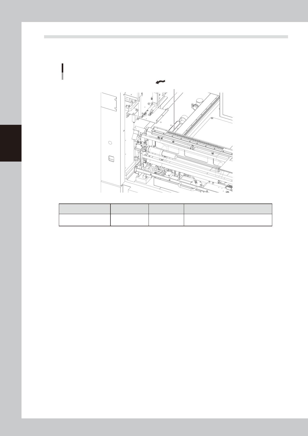
2.5 Suction-blower unit
2.5.1 Blower hose guide
Lubrication points in suction blower unit
Each table
blower hose guide
53310-N3-00
Lubrication section Lubrication point Interval Procedure
Blower hose guide 1 (Each table)
When hose is
replaced
Manual lubrication

A-1
Appendix
1. Specifications
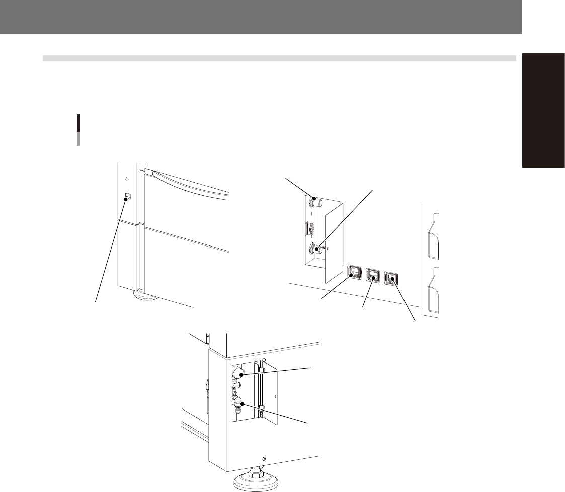
1.1 Air regulator unit
The air regulators and related components for controlling the air pressure to the pneumatic units of this
machine are located on the front and rear of the machine. The air pressure regulator must be correctly set to
supply the machine at an optimum air pressure.
Air regulator unit
Right-to-left flow machine
Source air connecto
Air supply/shutoff switch
■ Front left side of machine ■ Rear upper left of machine
■ Rear lower left of machine
Main pressure
gauge (1)
Main pressure
gauge(2)
Edge clamp pressure gauge
Main air pressure regulator (1)
Main air pressure regulator (2)
Cleaner negative
pressure gauge
53A01-N3-00
n
Supply air pressure
This is the pressure of the source air supplied to the machine. Before setting the air pressure with the air regulator, make
sure that this supply air pressure is in the following optimal range.
YSP20 : 0.45MPa
n
Air pressure display
Set air pressure level: 0.40MPa to 0.41MPa
This is shown in green when the pressure is normal, and turns red if a pressure drop is detected.
n
Edge clamp pressure gauge
Shows the edge clamp air pressure.
n
Cleaner negative pressure gauge
Shows the cleaner's vacuum air pressure level (negative pressure level).
n
Air supply/shutoff switch (valve)
Turning this switch to the right shuts off air supply and exhausts air that remains inside the machine.
n
Source air connector
Prepare an air hose with an inside diameter of at least 8 mm having a 30SH socket (Nitto Koki), and connect it to this
connector. Use dry and clean air that has been passed through the air dryer and air filter.