YSP20_Users_E.pdf - 第258页
2-14 2 Inspection and maintenance 3.3 Suction-blower unit T he suction-blower unit is alwa ys operated even when the mac hine is in emergency stop. It is therefore necessary to clean and replace the filter and replace th…
2-13
2
Inspection and maintenance
n
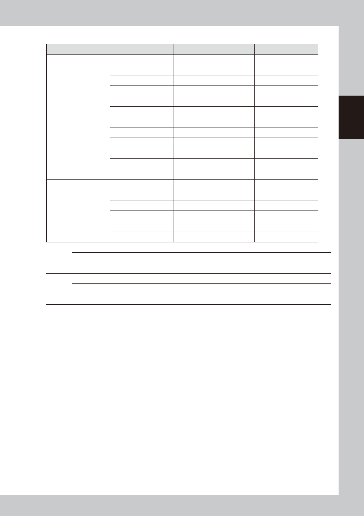
Double squeegee (Squeegee scraper)
Squeegee scraper Part No. Part name Q'ty Notes
Standard METAL W-SQG
KHT-M71C3-00X METAL SQG.,530 1 530mm
KGY-M71R3-01X METAL SQG.,440 1 440mm
KGJ-M7183-03X METAL SQG.,400 1 400mm
KGJ-M7173-03X METAL SQG.,350 1 350mm
KGJ-M71A3-01X METAL SQG.,300 1 300mm
KGJ-M7193-01X METAL SQG.,250 1 250mm
For half-etching METAL
W-SQG
KHT-M71C3-10X METAL SQG.(S),530 1 530mm
KGY-M71R3-10X METAL SQG.(S),440 1 440mm
KGJ-M7183-10X METAL SQG.(S),400 1 400mm
KGJ-M7173-10X METAL SQG.(S),350 1 350mm
KGJ-M71A3-10X METAL SQG.(S),300 1 300mm
KGJ-M7193-10X METAL SQG.(S),250 1 250mm
URETHANE W-SQG
KHT-M71E3-00X URETHANE SQG.,530 1 530mm
KGY-M71W3-00X URETHANE SQG.,440 1 440mm
KGJ-M710C-E0X SQUEEGEE,400 1 400mm
KW3-M7126-00X SQUEEGEE,M 1 350mm
KGJ-M71C3-00X URETHANE SQG.,300 1 300mm
KGJ-M71B3-00X URETHANE SQG.,250 1 250mm
c
CAUTION
Parts (Part No.) listed above is current as of the issue date of this manual. When ordering a replacement part, please
check for the latest information.
c
CAUTION
Part Nos. are subject to change without prior notice. When ordering a replacement part, contact your local sales
dealer to check its part No.
2-14
2
Inspection and maintenance
3.3 Suction-blower unit
The suction-blower unit is always operated even when the machine is in emergency stop. It is therefore
necessary to clean and replace the filter and replace the blower hose periodically.
3.3.1 Cleaning and replacing the filter
To clean and replace the filter, follow the steps below.
n
Required tools
• Phillips screwdriver
• Replacement filter (KGY-M3710-40X INL FILTER ELEMENT)
• Air blow tool (option)
1
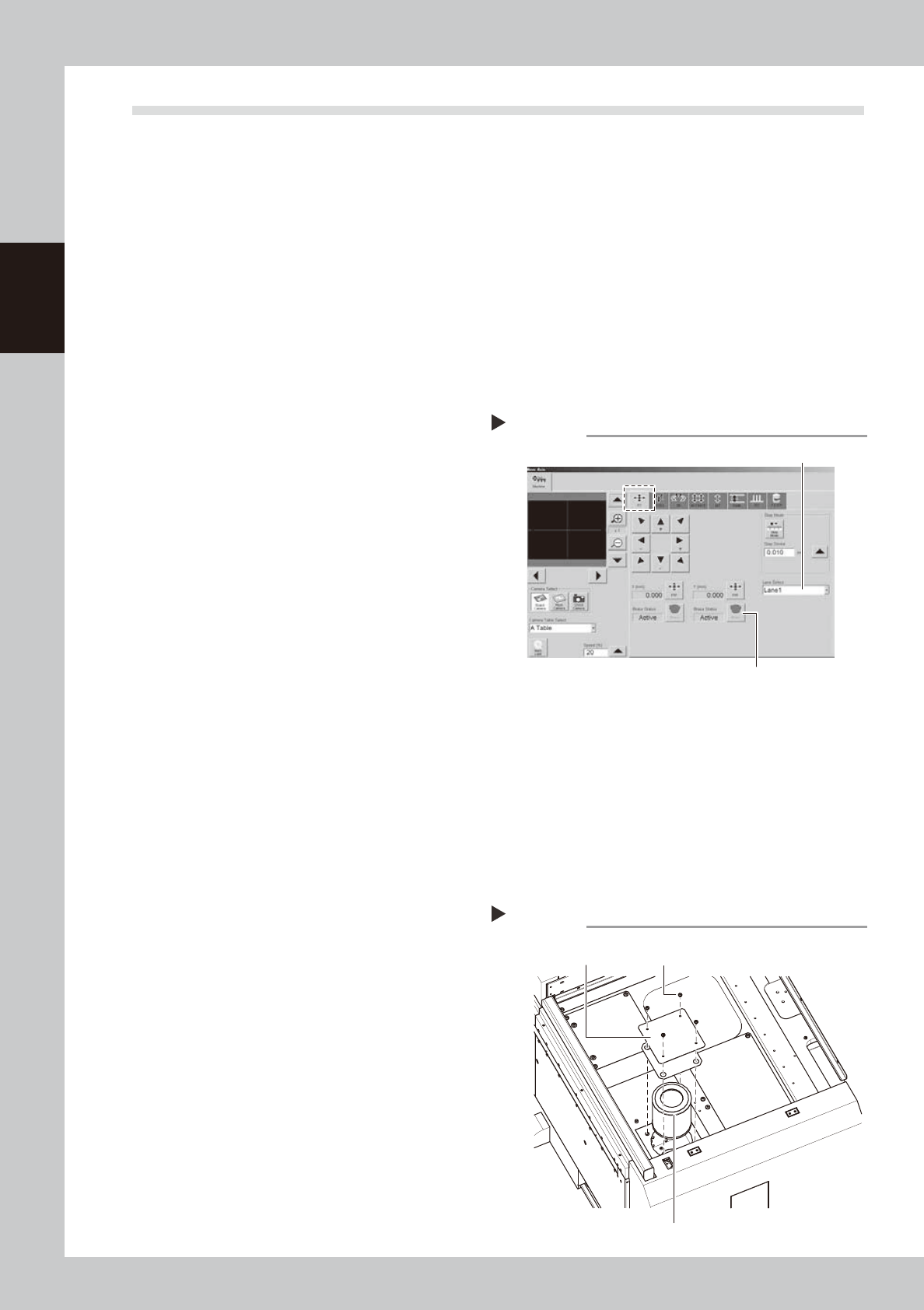
Perform return-to-origin.
e
2
Press the emergency stop button.
3
Release the Y-axis brakes on both
lanes.
1. On the [Unit]-[Conveyor] tab, press the
[Axis] to open the “Move Axis” screen.
2. Open the [XY] tab and select “Lane 1”
from the “Select Lane” drop-down list.
3. Press the [Brake] button for the Y-axis to
release the brake.
4. Select “Lane 2” and press the [Brake]
button to release the Y-axis brake on
Lane 2.
54204-N3-00
4
Open the safety cover and move
the Y-axis unit backward.
Open the safety cover of the machine side
you will service. Then move the Y-axis unit
backward until the filter underneath is
revealed.
5
Press the [Power Off] button.
Follow the message that appears on the
screen to select [Yes].
6
Continue the power off sequence.
The message, "Abort from Power Off
sequence?", will appear. Select [No].
7
Cancel the return-to-origin.
The message, "Do you want to return to
Origin?", will appear. Select [Cancel].
8
Turn off the power.
1. The message, "Close this operation?", will
appear. Select [OK].
2. Turn off the power switch.
9
Open the setup cover.
0
Remove the filter cover.
Use the Phillips screwdriver to remove the
four screws securing the cover, and remove
the cover.
53210-N3-00
Removing the filter cover
Step 10
Mounting screws (4 places)
Filter
Filter cover
[Move Axis] screen
Step 3
Select “Lane”.
Y-axis [Brake] button
2-15
2
Inspection and maintenance
q
Take out the filter and clean it.
Take out the ring filter and blow the air from
the inside of the filter with an air blow tool.
If there are heavy dust deposits in the filter,
replace it with a new filter.
w
Return the filter to its original
position.
Fit the filter into place and then reattach the
cover.
3.3.2 Replacing the blower hose
To replace the blower hose, follow the steps below.
n
Required tools
• Slotted screwdriver
• Hex wrench (4mm)
• Replacement blower hose (KKX-M3674-0XX TUBE 25)
e
1
Press the emergency stop button.
2
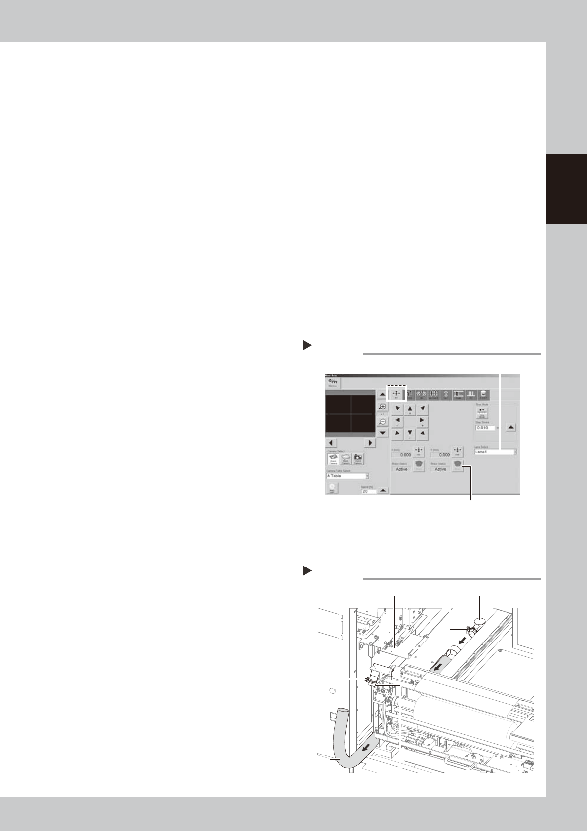
Release the Y-axis brakes on both
lanes.
1. On the [Unit]-[Conveyor] tab, press the
[Axis] to open the “Move Axis” screen.
2. Open the [XY] tab and select “Lane 1”
from the “Select Lane” drop-down list.
3. Press the [Brake] button for the Y-axis to
release the brake.
4. Select “Lane 2” and press the [Brake]
button to release the Y-axis brake on
Lane 2.
54201-N3-00
3
Open the safety cover and front
panel of the machine.
Open the safety cover and front panel on
the lane where you will replace the blower
hose.
4
Remove the blower hose from the
cleaner.
1. Move the unit on the Y-axis to the inner
end of the machine.
2. Loosen the hose band with a flat-blade
screwdriver and remove the blower hose
from the joint.
5
Remove the blower hose from the
blower.
1. Loosen the hose band with a flat-blade
screwdriver and remove the blower hose
from the joint.
2. Loosen the mounting bolts on the hose
clamps (2 bolts on each clamp) with an
Allen wrench (4mm).
3. Pull out the blower hose.
53211-N3-00
[Move Axis] screen
Step 2
Select “Lane”.
Y-axis [Brake] button
Removing the blower hose
Step 4,5
Hose bandHose band Hose clamp
Joint
Vacuum pipe
Blower hose