YSP20_Users_E.pdf - 第263页
Chapter 3 Lubrication points Contents 1. List of lubrication locations 3-1 1.1 Applicable grease 3-1 1.2 Grease gun 3-1 2. List of lubrication locations 3-2 2.1 X- and Y -axis 3-2 2.1.1 X1-axis and X2-axis 3-2 2.1.2 Y1-a…
2-18
2
Inspection and maintenance
3.5 Replacing the conveyor belt
The following describes how to replace the conveyor belt.
n
Required tools
• Hex wrench (3mm, 5mm)
• Fine brush
• Cleaning rag
• Replacement conveyor belt (KKX-M9124-00X BELT CONVEYOR)
e
1
Press the emergency stop button.
The machine must be in emergency stop to
ensure safety during work.
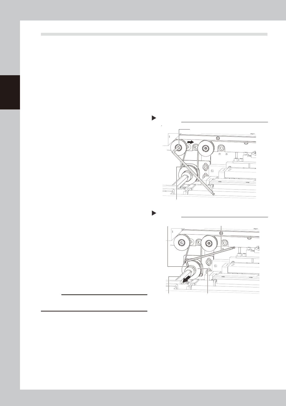
2
Slacken the belt.
Loosen the belt tensioner bolt with the hex
wrench (5mm) and slide the bolt fully along
the elongate hole (in the direction of
slackening the belt).
53214-N3-00
3
Detach the belt.
1. Use the hex wrench (3mm) to loosen the
mounting bolt securing the belt drive
pulley and pull the shaft away from the
pulley.
2. Detach the belt from the pulley and take
it out through the space between the
pulley and the shaft.
53215-N3-00
4
Detach the belt from the conveyor.
After you have detached the belt, clean the
clearance between the conveyor frame
and board guide with a fine brush or cloth
rag.
5
Attach a new belt.
1. Temporarily fit a new belt onto the pulley.
2. Reconnect the shaft to the pulley and
tighten the bolt.
3. Tighten the belt tensioner bolt while
applying a proper tension to the belt by
moving the belt tensioner bolt.
c
CAUTION
Always set the belt tensioner (pulley) tightening torque
at 5.5N•m.
6
Check the belt rotating condition.
1. Cancel emergency stop.
2. On the [Unit]-[Conveyor] tab, press the
[Left] and [Right] buttons to turn on the
conveyor motor and check the belt
rotation.
3. If the rotation speed fluctuates or there is
slack in the belt, adjust the position of
the tensioner bolt and then check the
rotation again.
Slackening the belt
Step 2
Tension adjustment bolt
Hex wrench (5mm)
Removing the shaft
Step 3
Drive pulley
Hex wrench (3mm)
Shaft
Mounting bolt

Chapter 3 Lubrication points
Contents
1. List of lubrication locations 3-1
1.1 Applicable grease 3-1
1.2 Grease gun 3-1
2. List of lubrication locations 3-2
2.1 X- and Y-axis 3-2
2.1.1 X1-axis and X2-axis 3-2
2.1.2 Y1-axis and Y2-axis 3-3
2.2 Printing head 3-4
2.2.1 SY-axis 3-4
2.2.2 SZ-axis 3-4
2.3 Mask table ASSY 3-5
2.3.1 MY-axis 3-5
2.3.2 MZ-axis 3-5
2.4 Conveyor unit 3-6
2.4.1 PU1-axis and PU2-axis 3-6
2.4.2 W1-axis and W2-axis (Conveyor auto width adjustment) 3-7
2.5 Suction-blower unit 3-8
2.5.1 Blower hose guide 3-8
3-1
3
Lubrication points
1. List of lubrication locations
This section describes the lubrication points of each unit as well as the lubrication intervals and procedures.
n
NOTE
See “Safety instructions” at the beginning of this manual for instructions on how to handle grease.
1.1 Applicable grease
When greasing the lubrication points, be sure to use appropriate grease specified by YAMAHA as listed below.
n
Specified grease
Parts List Designation
:
GREASE PACK (NSL)
Parts No. : K48-M3856-00X
c
CAUTION
If grease other than that specified is used, this may cause damage to the machine.
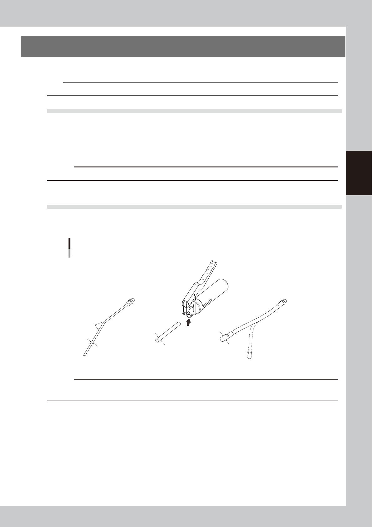
1.2 Grease gun
Select an appropriate nozzle suitable for the lubrication point from three kinds of nozzles shown below and
attach it to the grease gun to apply the grease. Change the nozzle according to the greasing instructions.
Grease gun
Grease gun
30°-bent type nozzle
Standard nozzle
Change the
nozzle here.
Chuck flexible type nozzle
30°
Outside diameter
of tip: φ14
Outside diameter
of tip: φ10
Outside diameter
of tip: φ5
53301-N3-00
c
CAUTION
Prepare different nozzles by grease. If two or more kinds of grease with different characteristics are mixed in the nozzle
and it is applied, this may cause the machine performance to lower.