YSP20_Users_E.pdf - 第229页
7-25 7 ther functions 4.6 [Unit]-[I/O] tab screen T he [Unit]-[I/O] tab screen allows you to chec k the I/O signal status and switch each output signal on or off. How to read this [I/O] tab screen is described below . …
7-24
7
ther functions
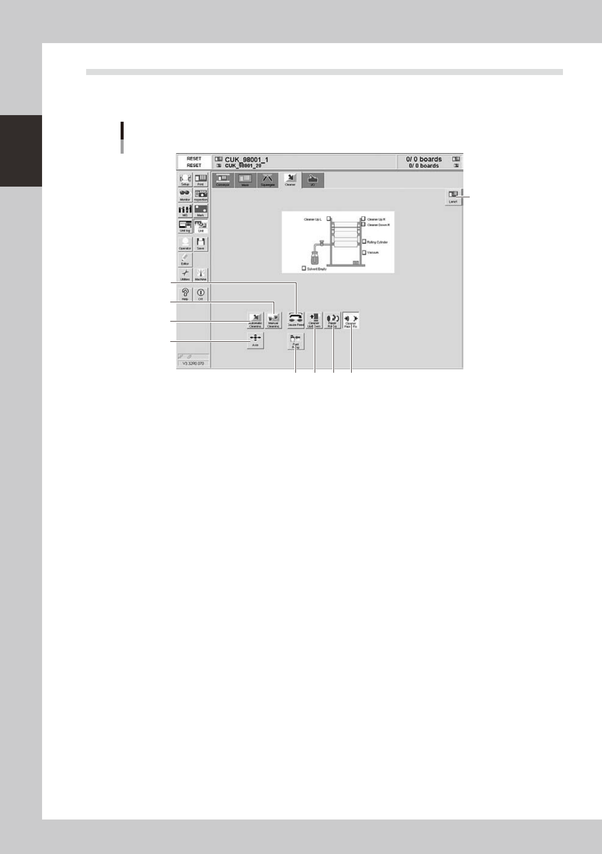
4.5 [Unit]-[Cleaner] tab screen
The [Unit]-[Cleaner] tab screen allows you to manually operate the cleaner unit and check the status of the
cleaner unit sensors on the graphic view. The function of each button is described below.
[Unit]-[Cleaner] tab screen
4
56 7
3
8
2
1
9
64722-N3-00
n
Operation buttons
1: [Axis] button
Opens the "Move Axis" screen. (See "4.1" in this chapter.)
2: [Automatic Cleaning] button
Press this button to automatically clean the backside of the mask.
3: [Manual Cleaning] button
Press this button when you want to manually clean the mask.
4: [Paper Rolling] button
Winds up the gauze roll (lower roll) at a specified pitch.
5: [Cleaner Paper Fix] button
Releases the gauze roll take-up shaft coupling. Pressing this button again, engages the take-up shaft coupling.
6: [Solvent Pump] button
Discharges a specified amount of cleaning solvent onto the gauze roll.
7: [Cleaner Up/Down] button
Moves the cleaner unit up or down.
8: [Gauze Feed] button
Feeds the gauze roll (upper roll) at a specified pitch.
9: [Lane] button
Changes between the board data for Lane 1 and Lane 2.
7-25
7
ther functions
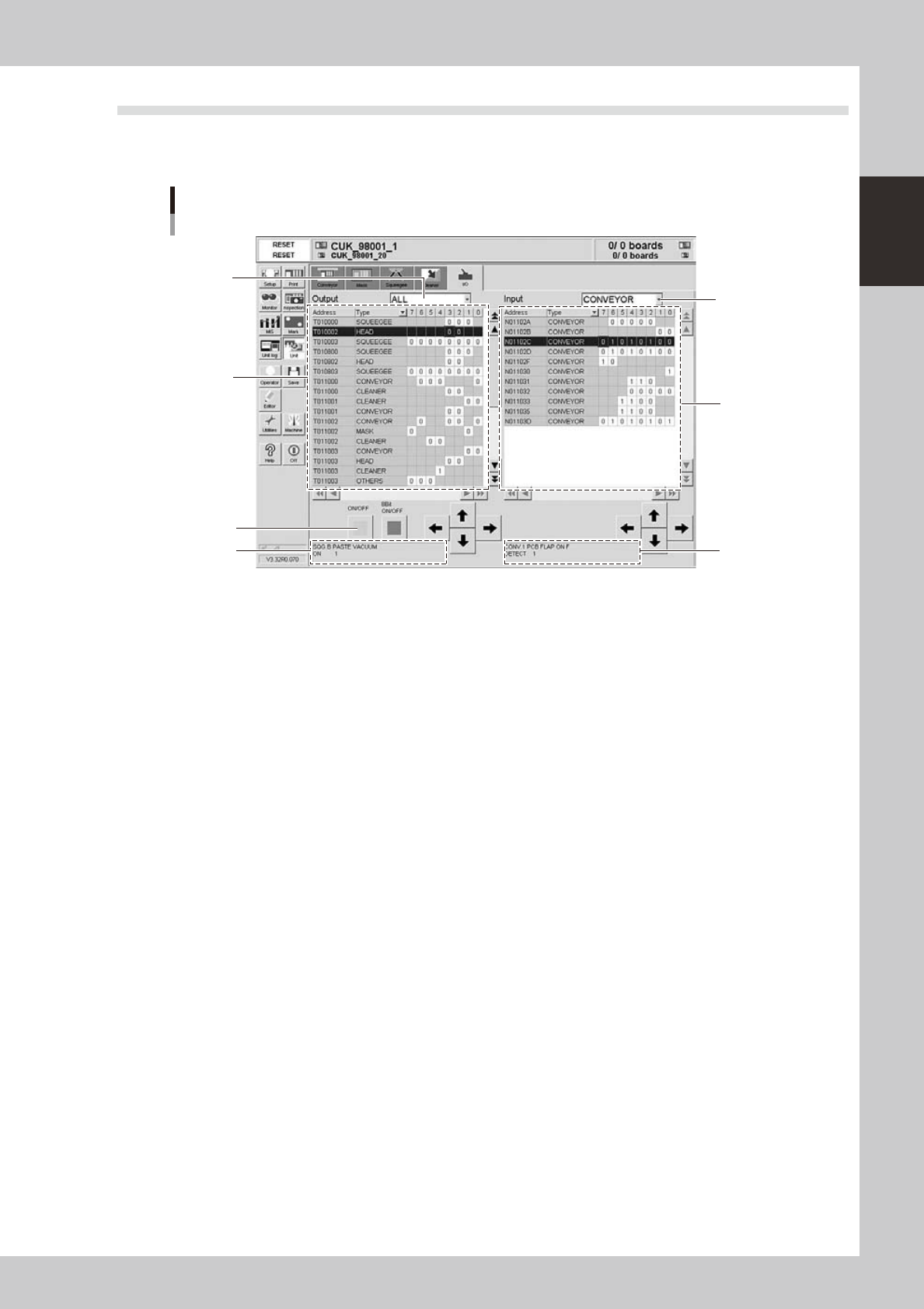
4.6 [Unit]-[I/O] tab screen
The [Unit]-[I/O] tab screen allows you to check the I/O signal status and switch each output signal on or off.
How to read this [I/O] tab screen is described below.
[Unit] - [I/O] tab screen
3
1
7
5
2 6
4
64723-N3-00
1: Output signal status
The status of each digital output signal is expressed in binary digits (1 and 0). Each signal is identified by a code name
consisting of an alphabet letter and numbers such as "T00275". To select each signal, click on it in the grid or click the
up/down and right/left arrow buttons to move the cursor there.
2: Output signal description box
Shows the name of the currently selected output signal and a description of what "0" and "1" mean.
3: Unit selection drop-down list
Select a unit from this drop-down list whose output signal status you want to display.
4: [ON/OFF] button
Clicking this button turns the currently selected signal on or off. (The [8bit ON/OFF] button is not currently used.)
5: Input signal status
The status of each digital input signal is expressed in binary digits (1 and 0). Each signal is identified by a code name
consisting of an alphabet letter and numbers such as "N005E0". To select each signal, click on it in the grid or click the
up/down and right/left arrow buttons to move the cursor there.
6: Input signal description box
Shows the name of the currently selected input signal and a description of what "0" and "1" mean.
7: Unit selection drop-down list
Select a unit from this drop-down list whose input signal status you want to display.

S-1
Index
A
[Adjust] button 7-13
Air supply/shut-off switch 1-1
Automatic stop 4-32
Backup pin arrangement 7-17
Backup pins 1-12
Basic data setting 5-3
Basic operation
Canceling emergency stop 2-1
Clearing an error 2-2
Starting the machine 2-11
Turning off the machine 2-13
[Board] button 4-4
Board check positions 5-10
Board clamp unit 1-11
Board data
Creating new data 5-1
Selecting the board data 4-4
Board data setting 5-5
Alignment 5-9
Board Datum Position 5-7,5-19
Board Size 5-6
Mark No. 5-12
Name 5-12
Origin 5-7
Print Feedback 5-9
Spin Timer 5-7
X, Y 5-6
Board distortion offset 5-10
board production
Finishing board production 4-32
Starting board production 4-23
[BUZZER OFF] button 2-2
C
CD-ROM drive 1-1
CE marking i
Cleaner data setting 5-26
Board count control 5-26
Dry Auto Interval 5-26
Dry Auto Repeat 5-26
Dry Auto Speed 5-26
Manual Interval 5-26
Time interval control 5-28
Wet Auto Interval 5-26
Wet Auto Repeat 5-26
Wet Auto Speed 5-26
Cleaning unit 1-18
Conveyor unit 1-11
Conveyor unit setup 4-5
[Convey-out Stop] button 4-32
[Create] button 5-1
Cursor teaching 7-8
[Cycle Stop] button 4-32
Daily operation flow 4-1
Data backup 6-1
Database 6-12
Dummy feeder iv
E
Emergency stop 2-1
Canceling emergency stop 2-1
Emergency stop button 4-32
Error
Clearing an error 2-2
Errors and troubleshooting 2-3
[ERROR CLEAR] button 2-2
FullASCII Output 6-22,6-28
G
Gauze roll 1-18,4-7
Replacing the gauze roll 4-7
Graphic alignment 5-40
I
Inspecting before operation 2-10
K
Keyboard 1-7
L
[Light] button 5-38
Lighting level 7-5
Light level 5-38
Liquid crystal touch screen 1-7
Local fiducial function 5-11
Machine operation history 6-23
Manual axis movement 7-20
Manual operation 7-18
Mark Adjust mode 5-30
[Mark] button 5-31
Mark data 5-30
Algorithm Type 5-35,7-13
Creating procedure 5-31
Cut Inner Noise 5-36
Cut Outer Noise 5-36
Light level 5-36
Mark Area 5-34
Mark Out Size 5-34
Mark Threshold 5-35
Mark Type 7-12
Outline 5-34
Search Area 5-36
Shape Type 5-33
Surface Type 5-35
Threshold level 5-39
Tolerance 5-36
Using the pattern matching 7-16
Mark data parameters 5-30
Mask 1-8
Mask check positions 5-16
Mask clamp 1-8
Mask clamp switch 1-8
Mask data setting 5-13
Mark No. 5-14
Mask Datum Position 5-15
Mask Name 5-14
Mask Origin 5-15
Mask parameters 5-14
Mask Size 5-14
Mask Standard Position 5-14
Mask Vacuum 5-15
Name 5-14
Standard Position Offset 5-15
X, Y 5-14
Mask Offset XY 5-47
[MIS]-[Board Log] tab 6-16
[MIS]-[Error Log] tab 6-14
[MIS]-[Program Log] tab 6-18
[Monitor] button 4-24
[Monitor]-[Detail] tab 4-27
[Monitor]-[Filling] tab 4-31
[Monitor]-[Vision] tab 4-28
Mouse 1-7
"Move Axis" screen 7-19
Move Squeegee 4-17
[Off] button 2-13,4-33
Operation panel 1-5
Operation panel buttons 1-6
[ACTIVE] button 1-6
[EMERGENCY STOP] button 1-6
[ERROR CLEAR] button 1-6
[READY] button 1-6
[RESET] button 1-6
[START] button 1-6
[STOP] button 1-6
Operation screen 2-15
[Operator] button 2-12
P
Page layout iii
Part names and functions 1-1
[Pattern] button 7-14
Pattern matching 7-16
Pattern registration 7-12
Point teaching 7-4
[Print]-[Board] tab 5-5
[Print]-[Cleaner] tab 5-26
Printing section 1-8
[Print]-[Mask] tab 5-13
[Print]-[Squeegee] tab 5-19
Production history 6-14
R
[READY] button 2-1
Refilling the cleaning solvent 4-12
Return-to-origin 2-11