YSP20_Users_E.pdf - 第41页
1-2 1 Part names and functions n Signal light Indicates current operating conditions of the mounter with a green, yello w and red light, or green, white and blue light explained below . (T he colors of the signal light c…
1-1
1
Part names and functions
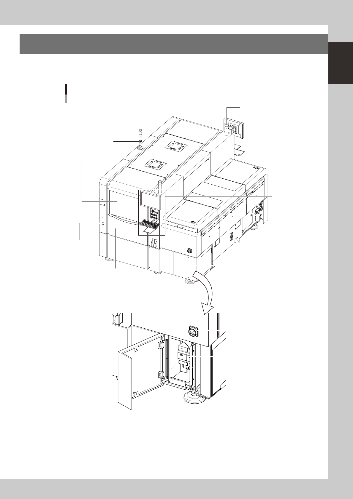
1. YSP20 main unit
A standard machine has the following configurations after installation. Names and functions of major parts
of the main unit are described on the subsequent pages.
YSP20 main unit
As viewed from front of RL (right-to-left flow) machine
Signal light
Operation panel
and data input unit
Power switch
Front lower right panel
Edge clamp
pressure gauge
Work instruction light
Buzzer
Power connection terminals
Front lower left panel
Front panel
Suction unit
(Behind right side panel)
Safety cover
63101-N3-00
1-2
1
Part names and functions
n
Signal light
Indicates current operating conditions of the mounter with a green, yellow and red light, or green, white and blue light
explained below. (The colors of the signal light can be selected from two patterns.)
Machine status Example Green
Red/
White
Yellow/
Blue
Warm-up or automatic operation ON ----- -----
Emergency stopor safety cover
switch activated
----- ON -----
System error
(with buzzer ON)
• Excessive current
• Secondary limit is exceeded
----- ON -----
Operation or board data error
(with buzzer ON)
• Error stop
• Stopped by interlock device
----- ----- ON
Materials cannot be used. Solder ----- ----- ON
Alarm buzzer
This buzzer sounds if an error or abnormal operation occurs. (The color of the signal light when a buzzer sounds can be
selected from two patterns (option). (The buzzer volume can be adjusted by turning the buzzer ring right or left.)
Safety cover
Opening this cover enters a state that allows non-stop changeover. Before opening this cover to change the mask (stencil),
squeegees, or solder type, make sure the DOOR LOCK lamp is OFF. Keep this cover closed during operation.
Edge clamp pressure gauge
Shows the air pressure for the edge clamp.
Printing section
Consists of a printing table and a squeegee head. See "3. Printing section" later in this chapter for more details.
Front panel
This panel contains the vision camera unit and conveyor unit. See "4. Conveyor unit" and "6. Vision camera unit" later in
this chapter for more details.
Cleaning unit and solvent tank (behind front and rear panelsr)
The cleaning unit uses a gauze roll to wipe away solder adhering to the mask apertures and solder coming out of the
backside of the mask while vacuuming. See "5. Cleaning unit" later in this chapter for more details.
Front lower left panel
The servo controller is located behind this panel. Keep this panel closed during operation.
Front lower right panel
Power connection terminals, transformer, and breaker are located behind this panel. Keep this panel closed during
operation.
Power switch
Turns the power to the machine on and off. The power is on when turned to the right.
c
Wait about 2 seconds before turning the Power switch back on after having turned it off.
Work instruction light
Lights up yellow to indicate the location (front or rear) where an error occurred or any material needs to be replenished.
Conveyor unit
The conveyor unit is located under the printing table. For details, see "4. Conveyor unit" in this chapter.
1-3
1
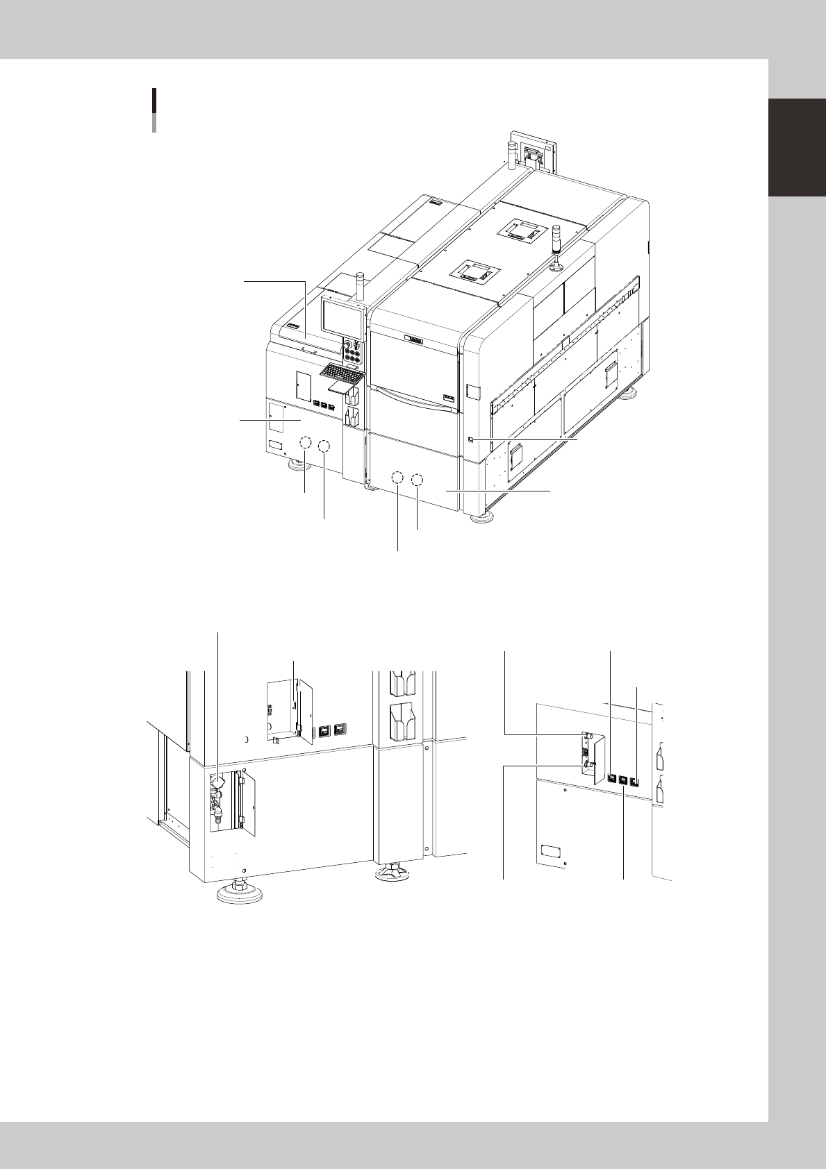
Part names and functions
YSP20 main unit
As viewed from rear of RL (right-to-left flow) machine
Cleaner vaccum
pressure gauge
Main pressure gauge (1)Main air pressure regulator (1)
Main pressure gauge (2)Main air pressure regulator (2)
USB port
Rear lower right panel
Rear lower left panel
Air supply/shut-off switch
Setup cover
Edge clamp
pressure gauge
Previous Interface (Lane 2)
Previous Interface (Lane 1)
Next Interface (Lane 2)
Next Interface (Lane 1)
63102-N3-00