YSP20_Users_E.pdf - 第277页
A-5 Appendix n Lane 2 When the following three conditions are met, the PREVIOUS INTERF A CE circuit in the machine allo ws the next board to be carried in. 1. Machine is read y for carrying in a board (BUSY OUT 2 : ON) 2…
A-4
Appendix
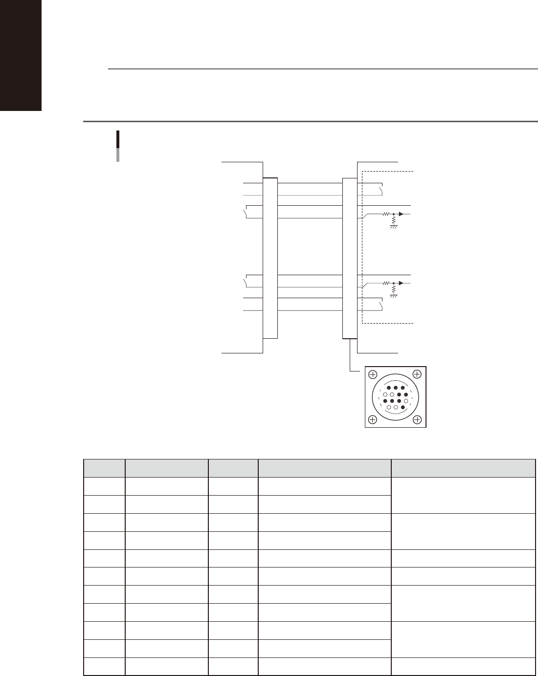
1.3.1 PREVIOUS INTERFACE connector
n
Lane 1
When the following three conditions are met, the PREVIOUS INTERFACE circuit in the machine allows the next
board to be carried in.
1. Machine is ready for carrying in a board (BUSY OUT: ON)
2. Board carry-in signal is input from the upstream machine. (BA IN [N0108221] : ON)
3. Automatic operation signal is input from the upstream machine. (UR IN [N0108222] : ON)
n
NOTE
• When the automatic operation signal (UR IN) from the loader turns off during transfer of a board, the machine
temporarily stops carrying in the board.
• When the board being carried in is detected by the entrance sensor, the BUSY OUT signal turns off.
• Carrying in the board is finished when both the BUSY OUT and BA IN turn off.
7
12
4
8
1
14
11
3
PREVIOUS INTERFACE circuit
Lane 1
This machine Upstream machine
PREVIOUS INTERFACE connector
BUSY OUT
(T01100E4)
BUSY IN
+24V
+24V
LR OUT
(T01100E7)
LR IN
UR IN
(N0110322)
UR OUT
BA IN
(N0110321)
BA OUT
I/O BOARD
1
2
3
4
5
6
7
8
9
10
11
12
13
14
53A05-N3-00
n
Board transfer signal specifications (PREVIOUS INTERFACE)
Pin No. Signal name Address I/O specifications Signal specifications
1 BUSY OUT T01100E4 Relay contact (zero voltage) output Signal output during board carry-in
2 BUSY OUT T01100E4 Relay contact (zero voltage) output
3 +24V Input common (+24V) Signal input of board carry-out request
4 BA IN N0110321 Voltage input
5 NC (with dummy pins) (Prevents misinsertion.)
6 to 8 NC
9 +24V Input common (+24V) Signal input during automatic operation
10 UR IN N0110322 Voltage input
11 LR OUT T01100E7 Relay contact (zero voltage) output Signal output during automatic operation
12 LR OUT T01100E7 Relay contact (zero voltage) output
13 to 14 NC
A-5
Appendix
n
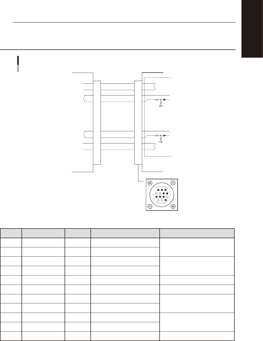
Lane 2
When the following three conditions are met, the PREVIOUS INTERFACE circuit in the machine allows the next
board to be carried in.
1. Machine is ready for carrying in a board (BUSY OUT 2 : ON)
2. Board carry-in signal is input from the upstream machine. (BA IN 2 [N01102A3] : ON)
3. Automatic operation signal is input from the upstream machine. (UR IN 2 [N01102A4] : ON)
n
NOTE
• When the automatic operation signal (UR IN 2) from the loader turns off during transfer of a board, the machine
temporarily stops carrying in the board.
• When the board being carried in is detected by the entrance sensor, the BUSY OUT 2 signal turns off.
• Carrying in the board is finished when both the BUSY OUT 2 and BA IN 2 turn off.
7
12
4
8
1
14
11
3
PREVIOUS INTERFACE circuit
Lane 2
This machineUpstream machine
PREVIOUS INTERFACE connector
BUSY OUT 2
(T110110)
BUSY IN 2
+24V
+24V
LR OUT 2
(T0110113)
LR IN 2
UR IN 2
(N01102A4)
UR OUT 2
BA IN 2
(N01102A3)
BA OUT 2
I/O BOARD
1
2
3
4
5
6
7
8
9
10
11
12
13
14
53A06-N3-00
n
Board transfer signal specifications (PREVIOUS INTERFACE)
Pin No. Signal name Address I/O specifications Signal specifications
1 BUSY OUT 2 T0110110 Relay contact (zero voltage) output Signal output during board carry-in
2 BUSY OUT 2 T0110110 Relay contact (zero voltage) output
3 +24V Input common (+24V) Signal input of board carry-out request
4 BA IN 2 N01102A3 Voltage input
5 NC (with dummy pins) (Prevents misinsertion.)
6 to 8 NC
9 +24V Input common (+24V) Signal input during automatic operation
10 UR IN 2 N01102A4 Voltage input
11 LR OUT 2 T0110113 Relay contact (zero voltage) output Signal output during automatic operation
12 LR OUT 2 T0110113 Relay contact (zero voltage) output
13 to 14 NC
A-6
Appendix
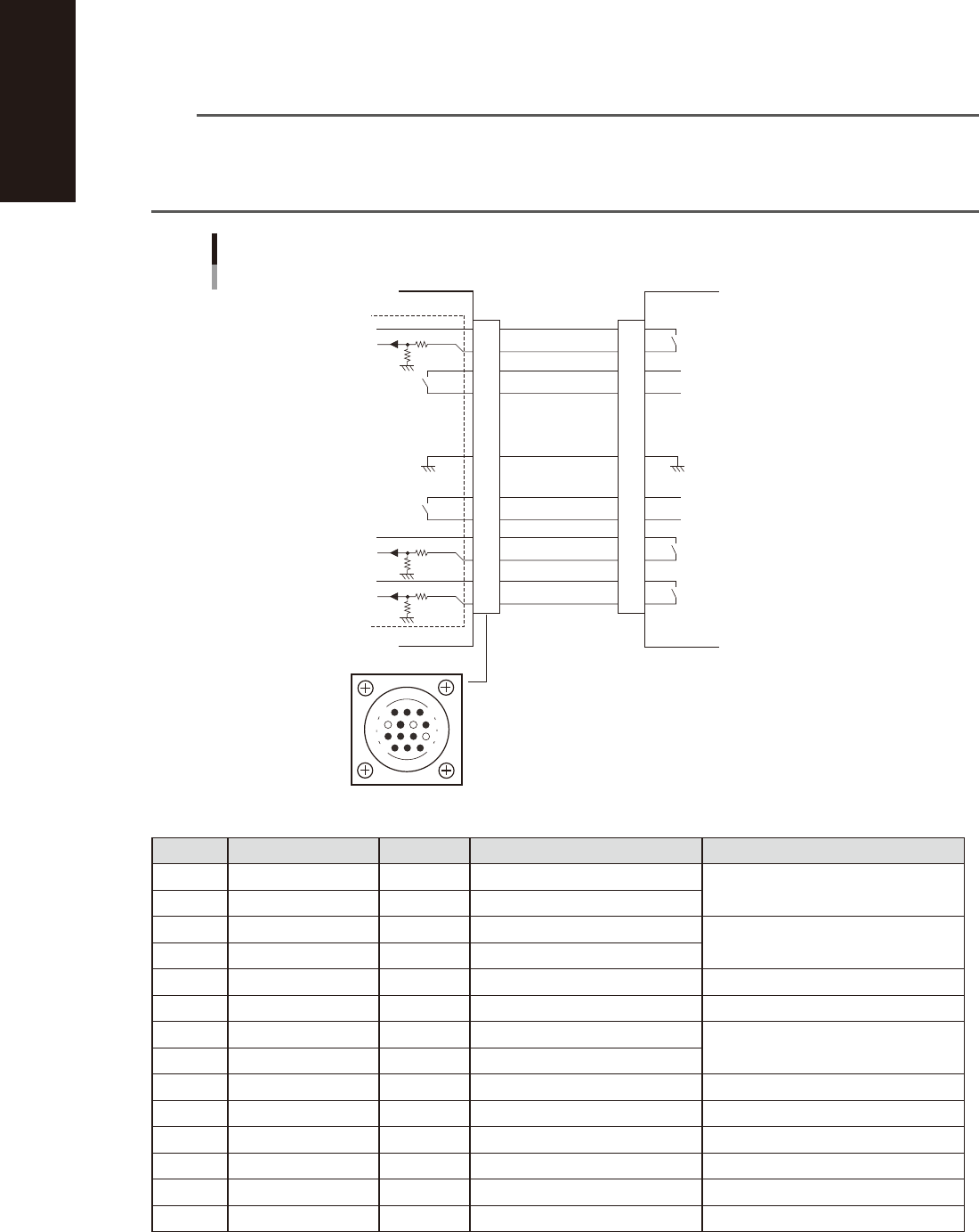
1.3.2 NEXT INTERFACE connector
n
Lane 1
When the following three conditions are met, the NEXT INTERFACE circuit in the machine allows the board to
be carried out.
1. Machine is ready for carrying out the board (BA OUT: ON)
2. Board carry-in signal is input from the downstream machine. (BUSY IN [N011320] : ON)
3. Automatic operation signal is input from the downstream machine. (LR IN [N0110323] : ON)
n
NOTE
• When the automatic operation signal (LR IN) from the downstream machine turns off during transfer of a board,
the machine stops temporarily carrying out the PC.
• When the board being carried out is detected by the exit sensor, the BA OUT signal turns off.
• Carrying out the board is finished when both the BUSY IN and BA OUT turn off.
14
11
12
7
4
8
3
1
NEXT INTERFACE circuit
Lane 1
NEXT INTERFACE connector
This machine
Downstream machine
BUSY IN
(N0110320)
BUSY OUT
+24V
+24V
UR OUT
(T01100E6)
LR IN
(N0110323)
+24V
LS IN
(N0110324)
UR IN
LR OUT
LS OUT
BA OUT
(T01100E5)
BA IN
I/O BOARD
GND GND
1
2
3
4
5
6
7
8
9
10
11
12
13
14
53A07-N3-00
n
Board transfer signal specifications (NEXT INTERFACE)
Pin No. Signal name Address I/O specifications Signal specifications
1 +24V Input common (+24V) Signal input during board carry-in
2 BUSY IN N0110320 Voltage input
3 BA OUT T01100E5 Relay contact (zero voltage) output Signal output to request board carry-out
4 BA OUT T01100E5 Relay contact (zero voltage) output
5 NC
6 NC (with dummy pins) (Prevents misinsertion.)
7 GND
8 NC
9 UR OUT T01100E6 Relay contact (zero voltage) output Signal output during automatic operation
10 UR OUT T01100E6 Relay contact (zero voltage) output
11 +24V Input common (+24V) Signal input during automatic operation
12 LR IN N0110323 Voltage input
13 +24V Input common (+24V) Lane select signal input
14
LS IN
N0110324 Voltage input