YSP20_Users_E.pdf - 第39页
Chapter 1 Par t names and functions T his chapter explains YSP20 major part names and functions. Make sure that you understand the location and function of eac h part before attempting machine operation. Contents …
iii
About this manual
1.3 Page layout
The description below shows a typical page layout used in this manual.
4-15
4
Daily operation
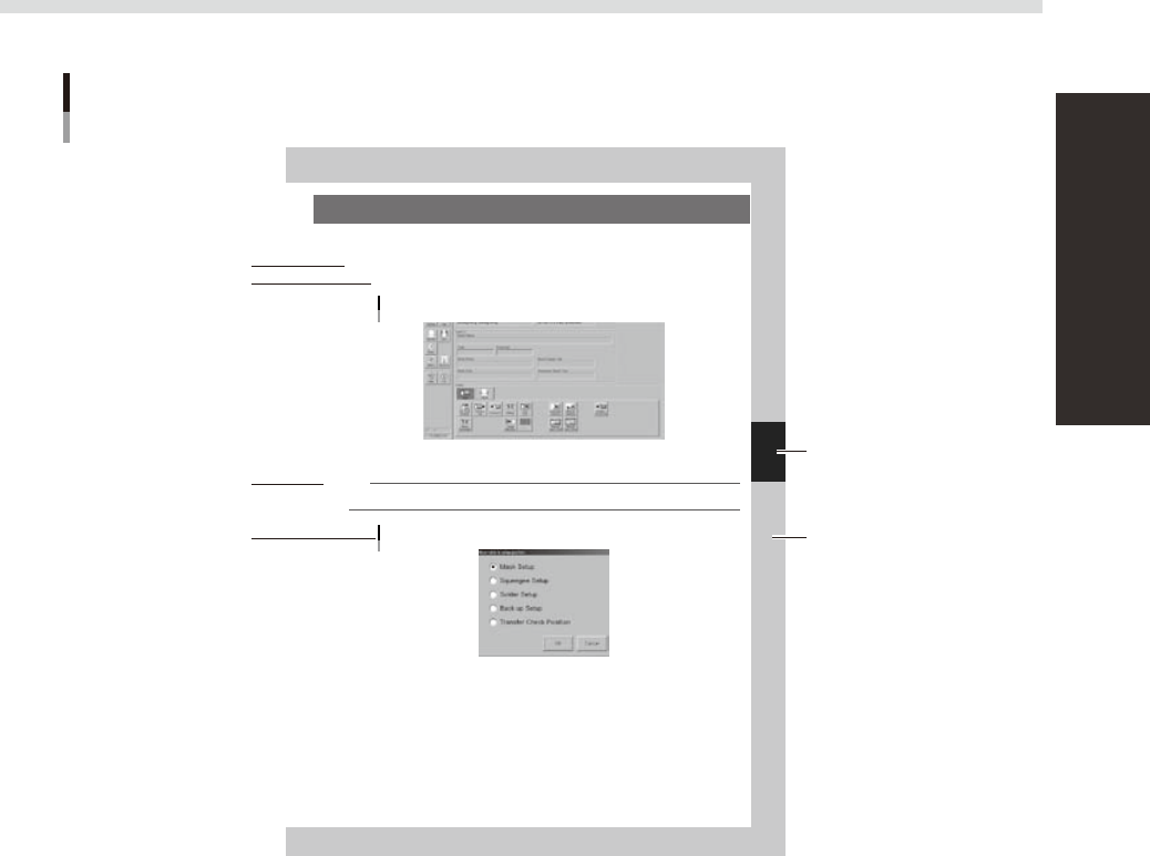
7. Setting up the mask and squeegee
This section explains procedures for clamping the mask (stencil) you have prepared on the printing table and
installing the squeegee onto the squeegee head.
On the Setup screen, open the [Setup] tab under “Utility”.
The buttons on this screen are used in the following steps to change the mask and squeegee setup.
Setup screen
[Setup] tab
64425-N3-00
Press the [SW. Prod. Position] button and select “Mask Setup”.
NOTE
When both lanes are used for production, the dialog box for selecting the lane number appears, so select the lane.
The lane currently used in production is grayed out.
Dialog box for move table to setup position
64426-N3-00
Typical page layout
Step
Chapter number
Chapter title
Sub step or
description of step
Figure, picture
or table caption
Note, Caution
or Warning
63003-L3-00
n
Step
This describes the procedure for each operation.
n
Substep or description of step
This provides detailed information on the steps in each procedure.
n
Figure, picture or table caption
This is the title of the illustration or table and appears at the upper left.
n
Note, Caution or Warning
These are explained in detail in "Safety instructions".

Chapter 1 Part names and functions
This chapter explains YSP20 major part names and functions. Make sure that you understand the location and function of each
part before attempting machine operation.
Contents
1
5
6
2.2 Keyboard and mouse 1-7
2.3 Liquid crystal touch screen (option) 1-7
3. Printing section 1-8
3.1 Squeegee head and printing table 1-8
3.2 3S squeegee 1-9
0
4. Conveyor unit 1-11
1
2
5
4.4 Conveyor layout 1-16
5. Cleaning unit 1-18
9
7. Servo-controlled axes 1-20
1-1
1
Part names and functions
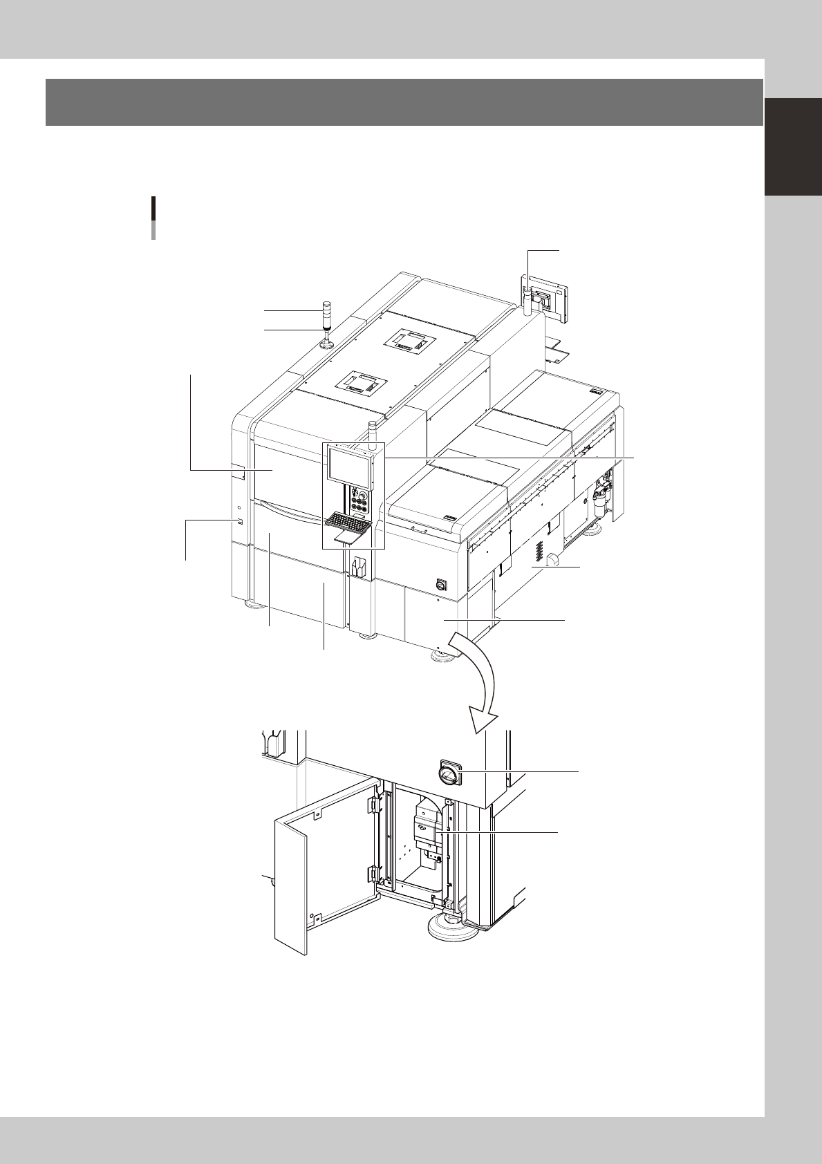
1. YSP20 main unit
A standard machine has the following configurations after installation. Names and functions of major parts
of the main unit are described on the subsequent pages.
YSP20 main unit
As viewed from front of RL (right-to-left flow) machine
Signal light
Operation panel
and data input unit
Power switch
Front lower right panel
Edge clamp
pressure gauge
Work instruction light
Buzzer
Power connection terminals
Front lower left panel
Front panel
Suction unit
(Behind right side panel)
Safety cover
63101-N3-00