YSP20_Users_E.pdf - 第83页
3-5 3 Printing guide 2.3 Rolling Rolling [Lane] button 64302-N3-00 1 Set the squeegee to be used. 2 Start the rolling operation. 1. Press the [Rolling] button, and follow the messages that appear on the operation s…
3-4
3
Printing guide
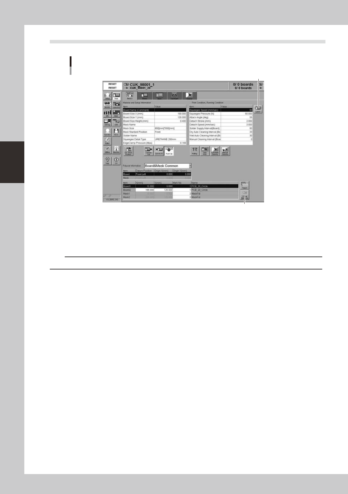
2.2 Alignment offset setting
Alignment offsets
[Visual Matching] button
[Lane] button
64301-N3-00
Press the [Visual Matching] button to open the Alignment Offset screen. Determine each offset value
while carefully checking the screen.
Since the graphic alignment is used for this alignment offset setting, set values in the [Mask Offset
X(mm)], [Mask Offset Y(mm)], and [Mask Offset R(DEG)] fields you can check on the screen.
n
NOTE
For more details about how to correctly use the graphic alignment, see "8. Graphic alignmentl" in Chapter 5.
3-5
3
Printing guide
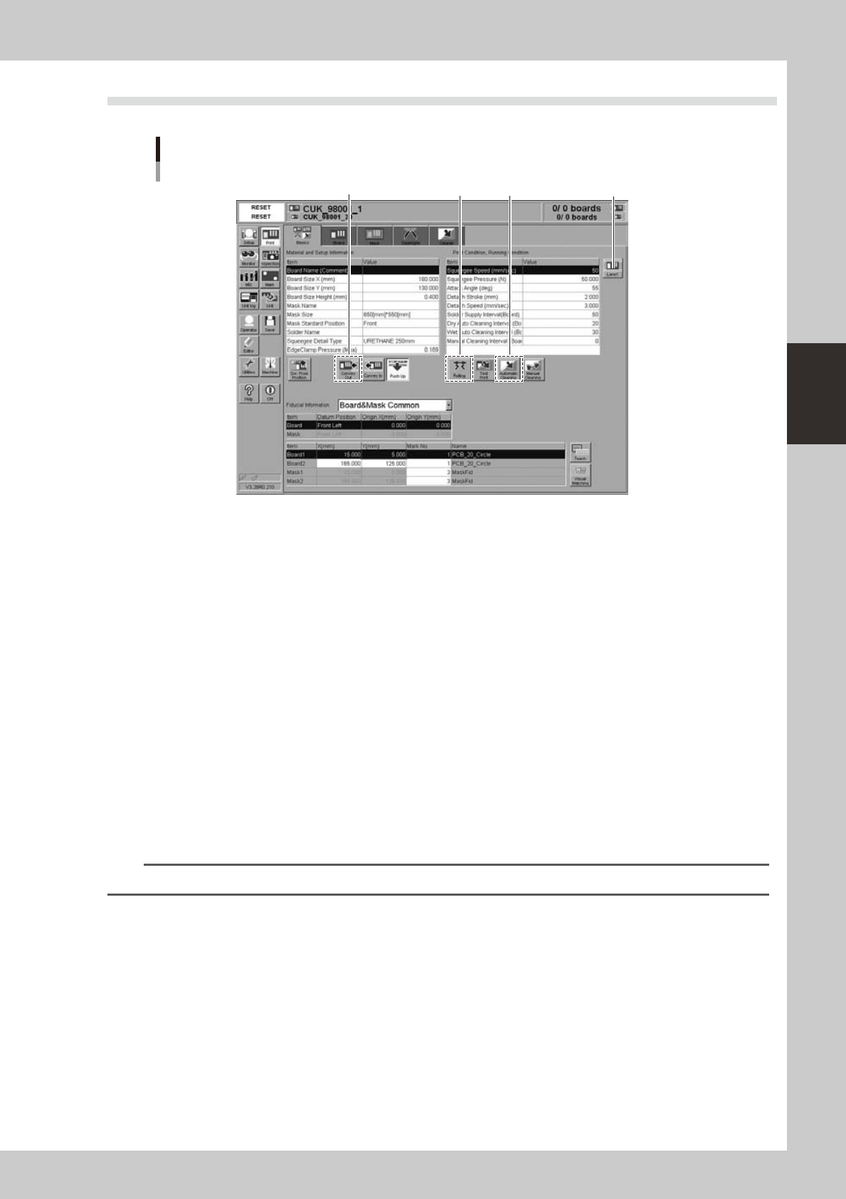
2.3 Rolling
Rolling
[Lane] button
64302-N3-00
1
Set the squeegee to be used.
2
Start the rolling operation.
1. Press the [Rolling] button, and follow the messages that appear on the operation screen to align the
board and mask positions. After the positions have been aligned completely, supply the solder. The
reference solder supply volume is one pod for a squeegee size of 530 mm. Based on this reference
volume, finely adjust the solder supply volume in accordance with the squeegee size.
2. Start the rolling. At this time, the squeegee pressure, squeegee speed, and attack angle are left set
at their default values.
3
Visually check the rolling condition.
l
If the solder slips:
If the rolling is not performed correctly due to solder slippage, decrease the squeegee speed.
l
If the scraped solder remains on the mask apertures:
Increase the printing pressure level or decrease the squeegee speed.
When no problem is found in the rolling and solder scraping condition, end the rolling operation.
4
Clean the mask by following the message on the screen.
Select the cleaning method (“Dry”, “Wet” or “Detail …1 to 4”) and press the [OK] button.
TIP
For information on the “Detail …1” to “Detail …4” settings, see "6. Cleaner data setting" in Chapter 5.
5
Unload the board by following the message on the screen.
3-6
3
Printing guide
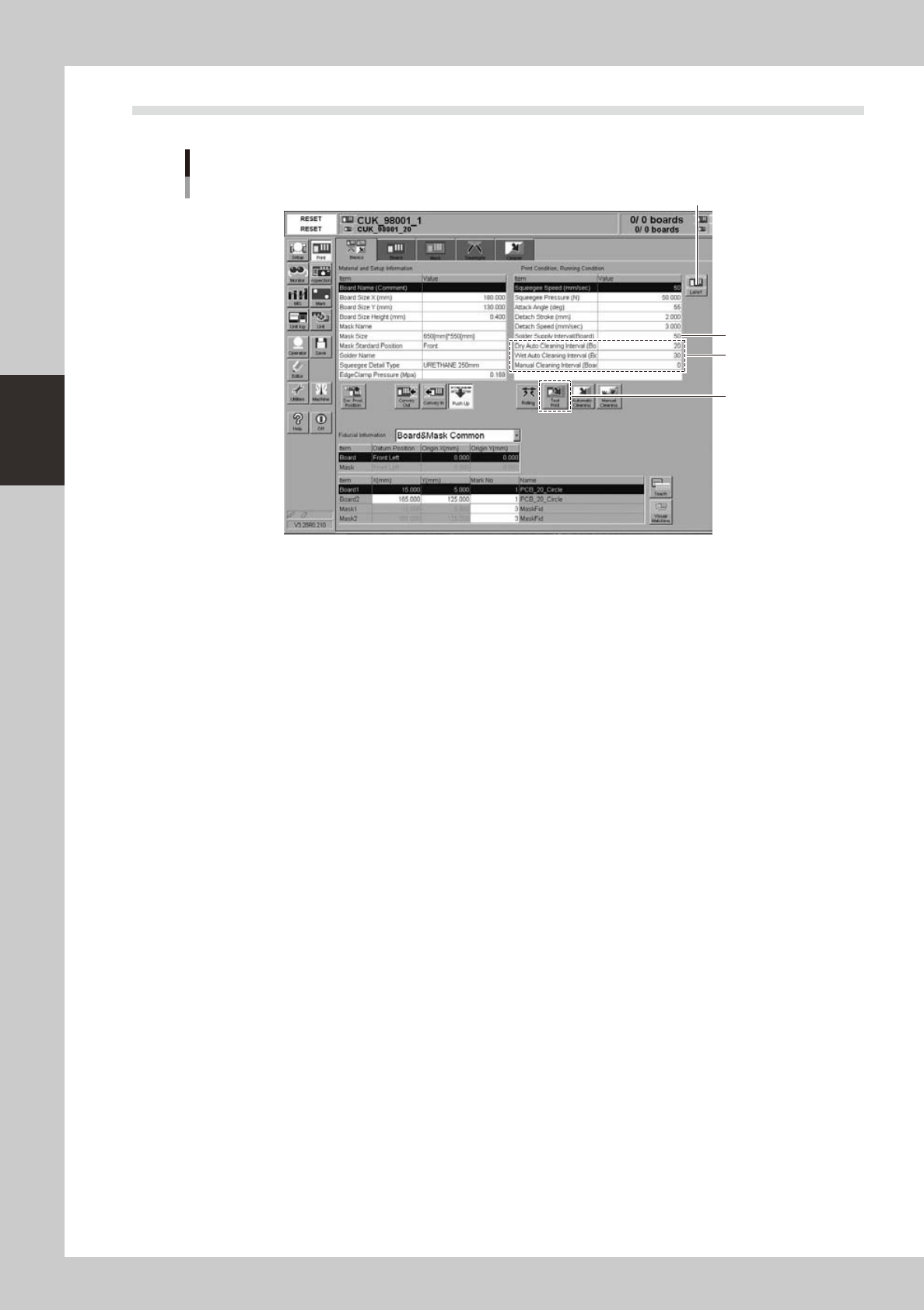
2.4 Printing and production conditions
Printing and production conditions
[Lane] button
64303-N3-00
1
Start the test print.
1. Press the [Test Print] button. Follow the messages that appear on the operation screen to load a
board, perform the printing, and unload the board.
2. Visually check the printed board.
3. If any print trouble is found, change relevant conditions by referring to "4. Causes of troubles
predicted from symptoms" in this chapter.
4. Start the test print again with the condition data you have changed.
2
Set cleaning conditions.
1. Enter a numeric value in the [Cleaning Interval] field. At this time, when the value is set at “0”, the
cleaning is not performed.
2. Start the cleaning with the cleaning speed and cleaning repeat set at their initial values. If you want
to change the value in the [Cleaning Speed] or [Cleaning Repeat] field, set the value on the
[Cleaner] tab screen.
Enter values as described above and start the production. If any print trouble caused by cleaning
occurs, change the values appropriately.
3
Set a solder supply interval.
Set how many boards are printed by one solder supply operation.
Normally, enter the number of boards that may consume 10 to 20% of the solder supply volume.