YSP20_Users_E.pdf - 第59页
1-20 1 Part names and functions 7. Ser vo-controlled axes The mechanical units of this machine move along the following ser vo-controlled axes. Other mechanical devices are driven by compressed air . n Dual-lane Plus dir…
1-19
1
Part names and functions
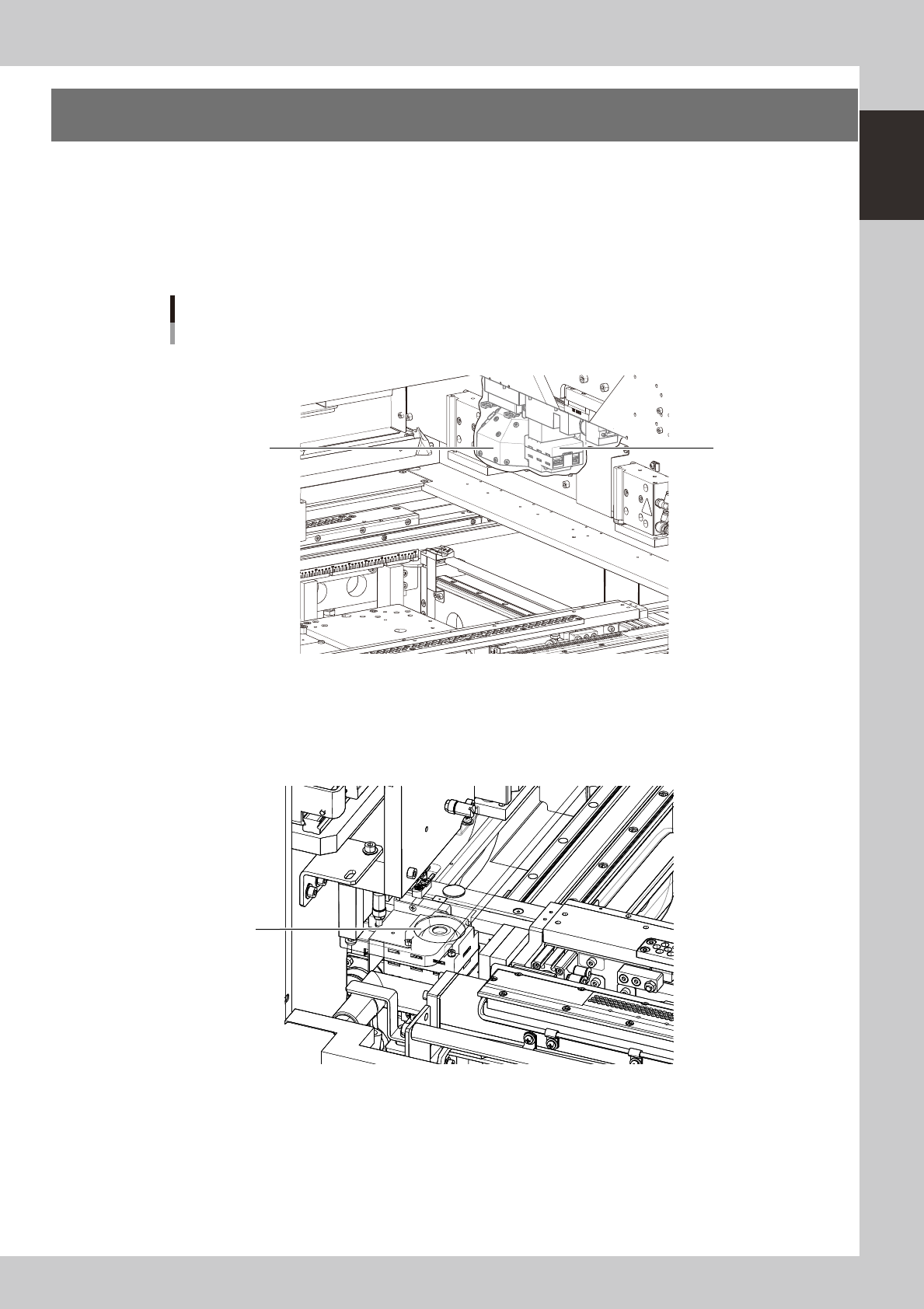
6. Vision camera unit
This machine is equipped with a "board vision camera" for recognizing fiducial marks and land patterns on
boards; and a "mask vision camera" for recognizing fiducial marks on the backside of masks (stencils) and
mask apertures. These cameras are also used as a teaching unit to perform teaching.
A "solder-print inspection camera" is added to machines which have the optional solder-print inspection
function.
These cameras are used as a teaching unit to perform the teaching.
Vision camera unit
1
3
2
N Front right side
N Front left side
As viewed from front of RL (right-to-left flow) machine
63123-N3-00
1. Board vision camera, Lighting unit
This vision camera and lighting unit recognize the surface of a board clamped on the conveyor.
2. Solder-print inspection camera (option), Lighting unit (option)
High-resolution, wide field-of-view camera and lighting unit installed in the YSP with an optional solder-print inspection
function. Refer to the separate "Option manual" for detailed information.
3. Mask vision camera, Lighting unit
This vision camera and lighting unit recognize the backside of a mask (stencil) clamped on the printing table.
1-20
1
Part names and functions
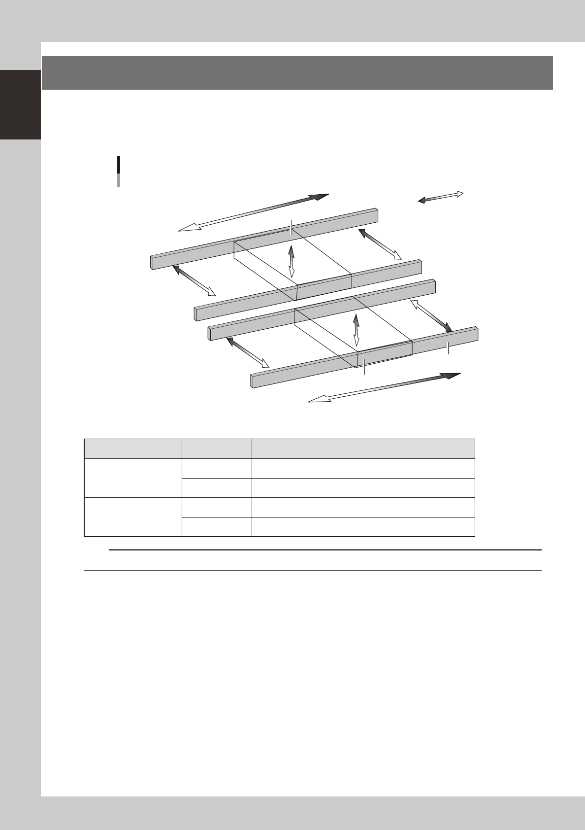
7. Servo-controlled axes
The mechanical units of this machine move along the following servo-controlled axes. Other mechanical
devices are driven by compressed air.
n
Dual-lane
Plus direction
Minus direction
W2-axis
Axis configuration
Lane 1
Lane 2
W1-axis
Y1-axis
Y2-axis
PU1-axis
PU2-axis
X2-axis
X1-axis
Conveyor rail
Board clamp unit (Board clamp table)
Board clamp unit (Board clamp table)
63124-N3-00
n
Axis functions
Unit name Axis Function
Board clamp unit
(Board clamp table)
X1, X2 Moves the board clamp table along the X-axis.
PU1, PU2 Raises and lowers the push-up plate.
Conveyor
Y1, Y2 Moves the conveyor unit along the Y-axis.
W1, W2 Adjusts the conveyor width.
TIP
You can manually move each unit on the operation screen. See "4.1 Move Axis screen" in Chapter 7 for more details.
1-21
1
Part names and functions
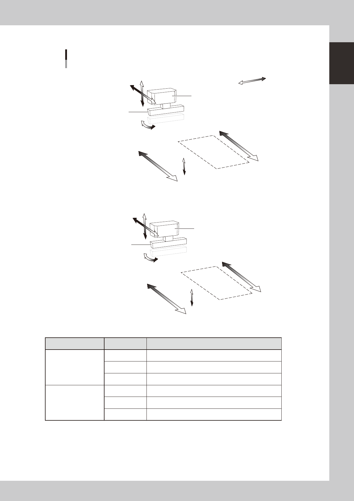
n
Table
Axis configuration
Squeegee
Squeegee head
Mask
Mask
SRA-axis
SYA-axis
SZA-axis
Plus direction
Minus direction
MYA2-axis
MYA1-axis
MZA-axis
Squeegee
Squeegee head
SRB-axis
SYB-axis
SZB-axis
MYB2-axis
MYB1-axis
MZB-axis
N Table A
N Table B
As viewed from front of RL (right-to-left flow) machine
63125-N3-00
Unit name Axis Function
Squeegee head
SY Moves the squeegee head parallel to the Y-axis.
SZ Moves the squeegee head vertically.
SR Adjusts the squeegee scraper angle. (3S head only)
Printing table
MY1 Moves the mask stage along the Y-axis.
MY2 Moves the mask stage along the R-axis.
MZ Adjusts the mask stage along the Z-axis.