YSP20_Users_E.pdf - 第108页
4-16 4 aily operation 3 When the DOOR L OCK lamp turns off , open the safety cov er . 4 Check or change the mask stopper pin position. If you are using a mask whose frame size is different from the mask previously used…
4-15
4
aily operation
7. Setting up the mask and squeegee
This section explains procedures for clamping the mask (stencil) you have prepared on the printing table and
installing the squeegee onto the squeegee head.
1
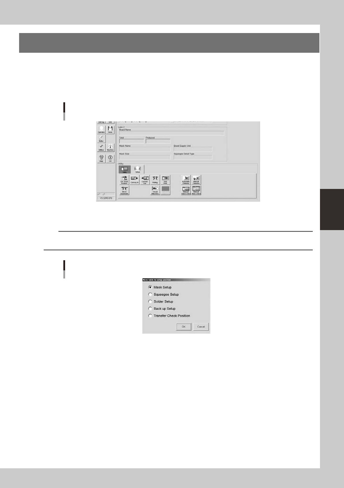
On the Setup screen, open the [Setup] tab under “Utility”.
The buttons on this screen are used in the following steps to change the mask and squeegee setup.
Setup screen
[Setup] tab
64425-N3-10
2
Press the [SW. Prod. Position] button and select “Mask Setup”.
n
NOTE
When both lanes are used for production, the dialog box for selecting the lane number appears, so select the lane.
The lane currently used in production is grayed out.
Dialog box for move table to setup position
64426-N3-00
4-16
4
aily operation
3
When the DOOR LOCK lamp turns off, open the safety cover.
4
Check or change the mask stopper pin position.
If you are using a mask whose frame size is different from the mask previously used, you must change
the mask stopper pin position on the left side of the printing table (W and L). Screw the mask stopper pin
into the correct hole by referring to the diagram affixed to the side of the mask stage or Appendix 7.1,
"Mask size and mask stopper pin position" in this chapter.
Mask stopper pin
L direction
Mask stopper pin
Put it here when do not
use the mask stopper pin.
63416-N3-00
5
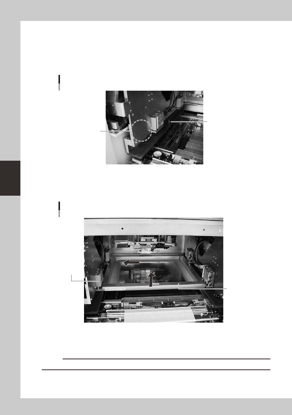
Bring the mask in contact with the stopper.
While keeping the mask frame horizontal, fully insert it in against the left stopper pins along the rear
stopper pins on the printing table.
Mask frame setup
Mask clamp
Mask frame
63417-N3-00
6
Clamp the mask.
With the mask kept in contact with the left corner on the rear of the printing table, turn the mask clamp
switch located on the right of the machine clockwise to clamp the mask.
c
4-17
4
aily operation
7
Move the squeegee head to the attach/detach position.
1. After closing the safety cover and pressing the [READY] button, press the [Move Squeegee] button.
TIP
When both lanes are used for production, the dialog box for selecting the print table appears, so select the table.
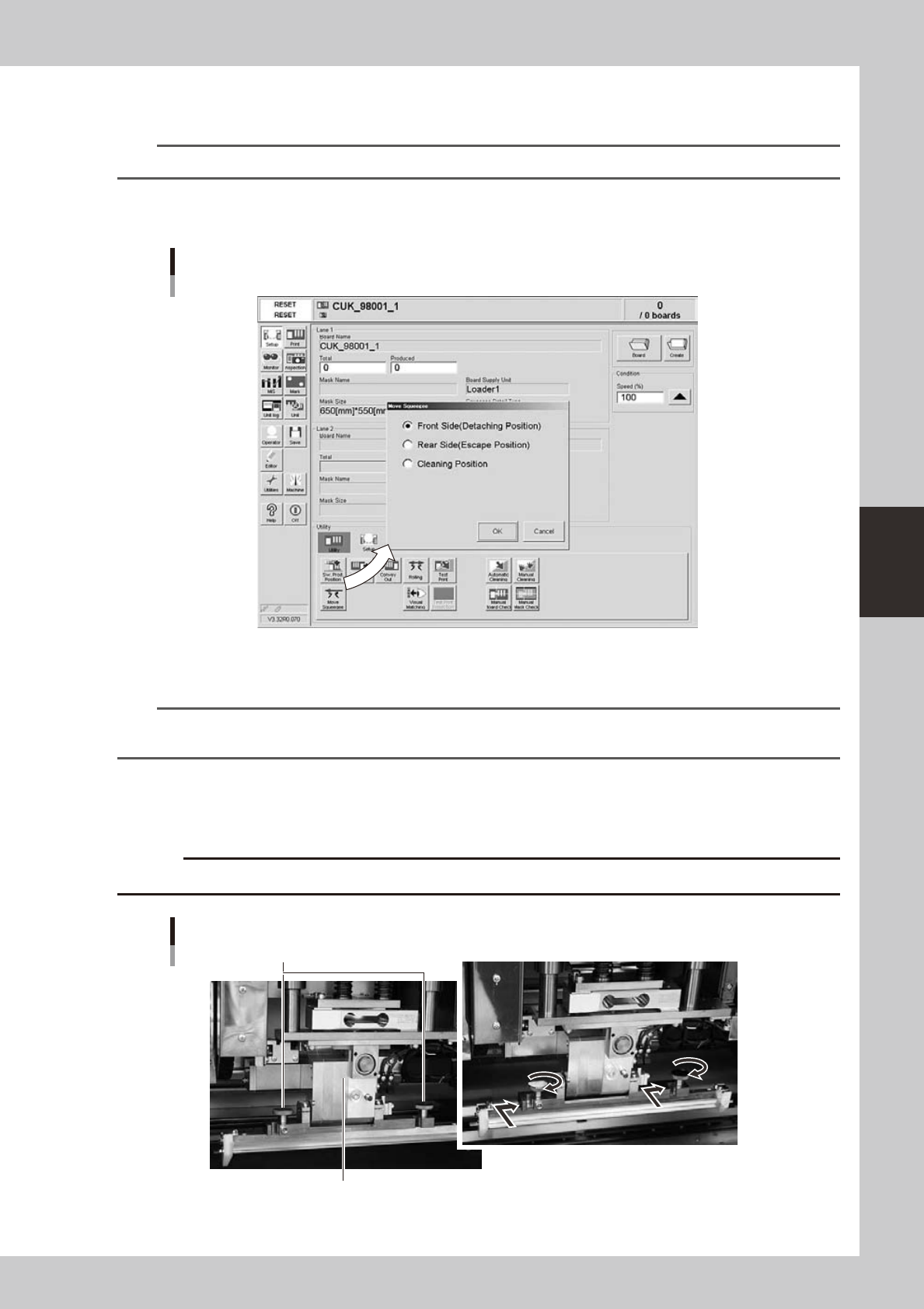
2. Select the "Front Side" position (attach/detach position) and press the [OK] button.
The squeegee head moves to the front side (towards you).
Squeegee position dialog box
64409-N3-10
8
Press the [SW. Prod. Position] button and select “Mask Setup”.
n
NOTE
When both lanes are used for production, the dialog box for selecting the lane number appears, so select the lane.
The lane currently used in production is grayed out.
Select “Squeegee Setup”. When the DOOR LOCK lamp turns off, open the safety cover.
9
Install the squeegee to the squeegee head.
Fit the mount knobs into squeegee head holder and tighten them as below.
c
Attaching the 3S squeegee
Mount knobs
Squeegee holder
63418-N3-00