YSP20_Users_E.pdf - 第149页
5-23 5 Creating and setting the data 5.1 Squeegee detail setting When you press the [Detail] button on the [Print]-[Squeegee] tab, the follo wing dialog box appears for adjusting the solder fill amount and setting the ti…
5-22
5
Creating and setting the data
S: F. Mask Offset R (deg)
When printing in the forward direction (from the front side to the inner side), the mask surface may stretch in the
advancing direction, causing a R-direction shift versus the land patterns. To correct this positional shift, enter an offset
value here.
If shifted counterclockwise : Enter a plus offset value.
If shifted clockwise : Enter a minus offset value.
T: B. Mask Offset X (mm)
When printing in the backward direction (from the inner side to the front), the mask surface may stretch in the advancing
direction, causing a X-direction shift versus the land patterns. To correct this positional shift, enter an offset value here.
This parameter is disabled when the "F. & B. Mask Offset" is set to "Same Offset".
If shifted in the plus direction : Enter a plus offset value.
If shifted in the minus direction : Enter a minus offset value.
U: B. Mask Offset Y (mm)
When printing in the backward direction (from the inner side to the front), the mask surface may stretch in the advancing
direction, causing a Y-direction shift versus the land patterns. To correct this positional shift, enter an offset value here.
This parameter is disabled when the "F. & B. Mask Offset" is set to "Same Offset".
If shifted in the plus direction : Enter a plus offset value.
If shifted in the minus direction : Enter a minus offset value.
V: B. Mask Offset Z (mm)
When printing in the backward direction (from the inner side to the front), the mask surface may stretch in the Z
direction. Enter this offset here. Leave this parameter set to "0.000" in most cases. This parameter is disabled when the "F.
& B. Mask Offset" is set to "Same Offset".
W: B. Mask Offset R (deg)
When printing in the backward direction (from the inner side to the front), the mask surface may stretch in the advancing
direction, causing an R-direction shift versus the land patterns. To correct this positional shift, enter an offset value here.
This parameter is disabled when the "F. & B. Mask Offset" is set to "Same Offset".
If shifted counterclockwise : Enter a plus offset value.
If shifted clockwise : Enter a minus offset value.
w: Squeegee Up Speed (%)
Usually, set this parameter to “Standard”. If you want to change the squeegee rising speed, set it while checking the
solder spreading.
X: Escape Position
This is the escape position where the squeegee head moves back from the solder printing area so that you can make
setups on the mask or conveyor table such as for supplying solder or changing the conveyor unit setups. Set to "Standard
Position" in most cases. If you specify another position, select "Defined Position" and set the SY and SZ coordinates for
the "Escape Position SY and SZ" parameters.
Y, Z: Escape Position SY, SZ
If you want to specify the escape position where the squeegee head moves back from the solder printing area, enter the
desired SY and SZ (height) coordinates. Settings here will be valid only when the "Escape Position" parameter is set to
"Defined Position".
f: Detaching Position
Specify a detaching position of the squeegee head. Normally, set “Standard Position”. If you want to change the
detaching position of the squeegee head by the production board, set “Defined Position” and specify data in the
Detaching Position SY and SZ parameters.
g, h: Detaching Position SY, SZ
When the Detaching Position is set to “Defined Position”, specify a position (SY) and a height (SZ).
TIP
To check the Mask Offset amount (positional shift), see "9. Making a test print".
5-23
5
Creating and setting the data
5.1 Squeegee detail setting
When you press the [Detail] button on the [Print]-[Squeegee] tab, the following dialog box appears for
adjusting the solder fill amount and setting the timing that the board separates from the mask after printing.
Here you can also set the positions for graphic alignment. Detail settings can be edited by selecting the [Filling
(Dry)], [Filling (Wet)], [Filling (Manual)], [Detach Pattern] and [Visual Matching Point] tabs.
l
Filling Adjust
If you want to adjust the squeegee speed and pressure to compensate for the board solder fill amount just after mask
cleaning, make the necessary settings here while referring to the following description.
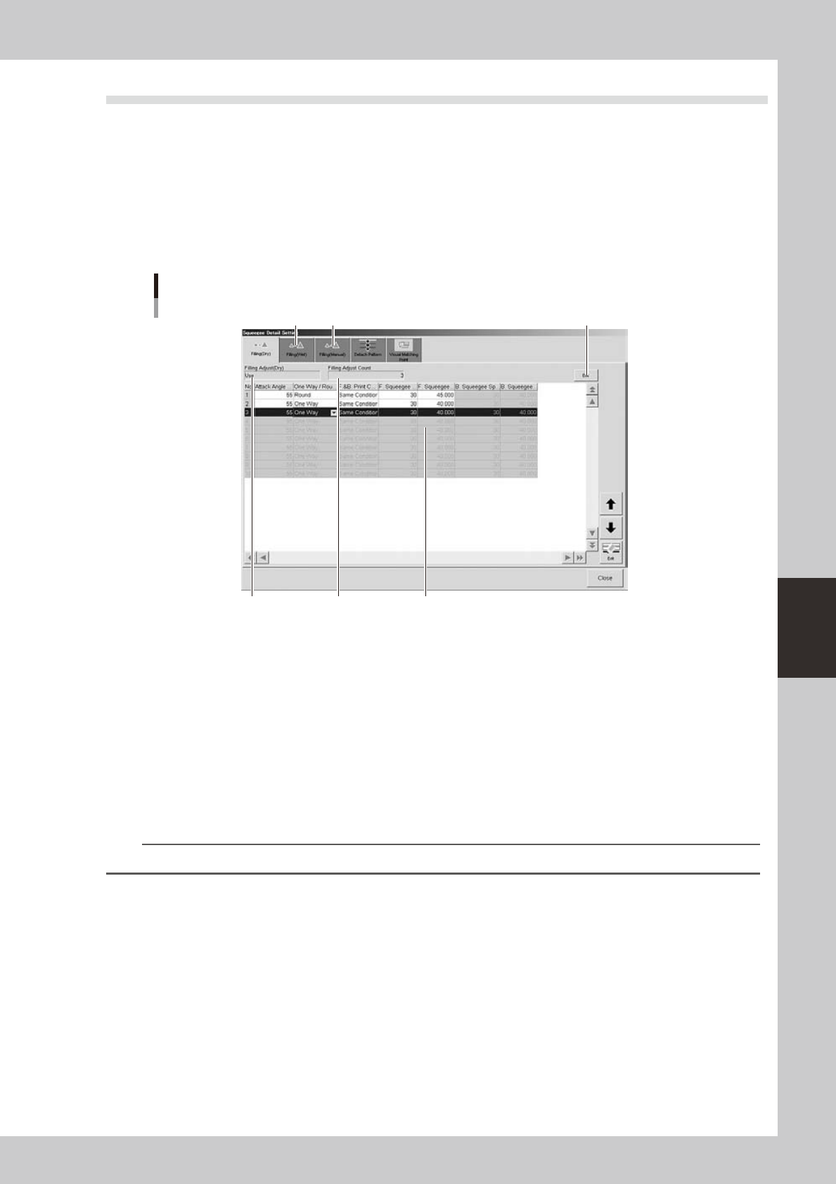
[Filling (Dry) ] tab
1
4
5
2 3
[Edit] button
64523-N3-10
1: Filling (Dry)
Set to "Use" when using this function. Set to "NotUse" if not using it. To change the setting, press the [Edit] button on the
right end.
2: Filling Adjust Count
Specify the number of boards on which you want to apply this function after mask cleaning. The data lines up to the
number of boards you specified become valid to allow data entry. Up to 10 boards can be specified. To change the
setting, press the [Edit] button on the right end.
3: Data grid display
Shows the squeegee speed and pressure parameters that were set on the [Print]-[Squeegee] tab. Change these parameter
values as needed. Merely increasing the printing pressure cannot increase the solder fill amount.
TIP
For details on each parameter setting, refer to "Printing Guide" at the end of this manual.
4: [Filling (Wet)] tab
If you want to adjust the squeegee speed and pressure to compensate for the board solder fill amount just after auto wet
cleaning, select this tab and make the necessary settings.
5: [Filling (Manual)] tab
If you want to adjust the squeegee speed and pressure to compensate for the board solder fill amount just after manual
cleaning, select this tab and make the necessary settings.
5-24
5
Creating and setting the data
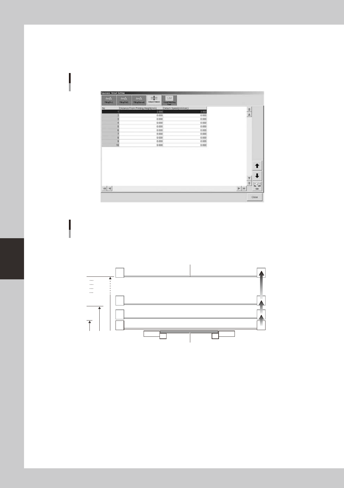
l
Detach Pattern
When you want to adjust the speed (mm/s) at which the board separates from the backside of the mask after solder
printing, set it at the distance (mm) from the backside of the mask. (Up to 10 steps can be set as needed.)
Set the optimal speeds by taking the solder type, mask, and board material into account.
[Detach Pattern] tab
64524-N3-10
Board separation setting
Board
Mask
No.1
No.2
No.10
Distance from
printing height
(0.01mm steps)
[0.001 to 7.000mm]
Board separation speed
(0.01mm/s steps)
[0.001 to 20.000mm/s]
63517-N3-00
l
If using sticky boards or jigs
If the surface (such as preflux board surface) that contacts the mask is sticking to it, then that board might stick to the
mask. If that happens the machine cannot see the board and triggers an error.
To deal with this problem, increase the board separation distance (from mask after printing) so that the board completely
separates from the mask. Change the default setting (2.00mm) for "Distance from printing height" in the above drawing,
to 3.00 to 4.00 mm or more.