YSP20_Users_E.pdf - 第97页
4-5 4 aily operation 4. Changing the conveyor unit setup When producing boards that are different from the previous production board, you need to change the conveyor unit setup to match the selected board. (This proced…
4-4
4
aily operation
3. Selecting the board data
To start board production, first select the board data from the list of board data already created beforehand.
1
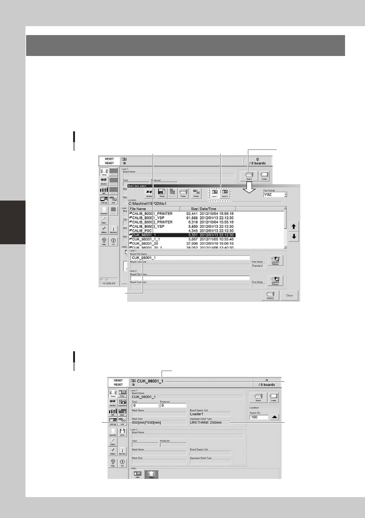
Select the board data.
1. When the board data is not yet selected, press the [Board] button on the Setup screen.
A list of board data appears.
2. Press the [Lane 1] or [Lane 2] button to select the lane for production. Then line up the cursor with
the board data name and press the [Select] button.
The machine loads the selected board data.
Selecting the board
Select board data from list.
Selected board data
name is displayed.
[Lane] button
[Board] button
64404-N3-00
2
Check the board data.
Check that the selected board data name is shown in the status area. Also check that the displayed
board size, mask size and squeegee type are correct.
Also check that the displayed mask size and squeegee type are correct.
Setup screen after selecting board data
Mask size
Squeegee type
Selected board
name
Board data for Lane 1
64405-N3-00
4-5
4
aily operation
4. Changing the conveyor unit setup
When producing boards that are different from the previous production board, you need to change the
conveyor unit setup to match the selected board. (This procedure is not necessary when you are producing
the same board as last time.)
c
1
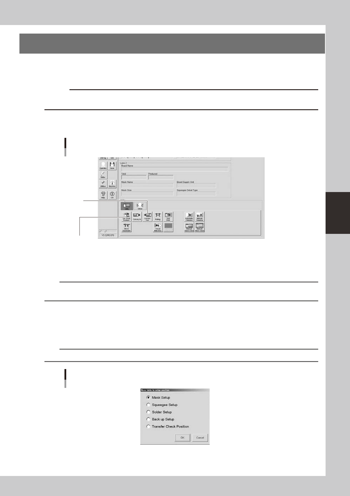
On the Setup screen, open the [Setup] tab under "Utility".
The buttons on this screen are used in the following steps to change the conveyor unit setup.
Setup screen
[Setup] tab
Step 2:
[SW. Prod. Position] button
Step 5:
[Convey In]
button
64406-N3-10
2
Press the [SW. Prod. Position] button.
Select the setup item.
n
NOTE
When both lanes are used for production, the dialog box for selecting the lane number appears, so select the lane.
The lane currently used in production is grayed out.
1. When rearranging the backup pins, select “Transfer Check Position”. The conveyor will move to the
setup position and the conveyor width will be automatically adjusted to match the board size.
2. When changing the whole matrix plate, select “Backup Setup”. The conveyor will move to the setup
position and the conveyor will be adjusted to the maximum width, allowing you to remove the matrix
plate.
n
NOTE
When removing the matrix plate, check for safety and then lift it straight up while holding firmly with both hands.
Dialog box for move table to setup position
64307-N3-00
4-6
4
aily operation
3
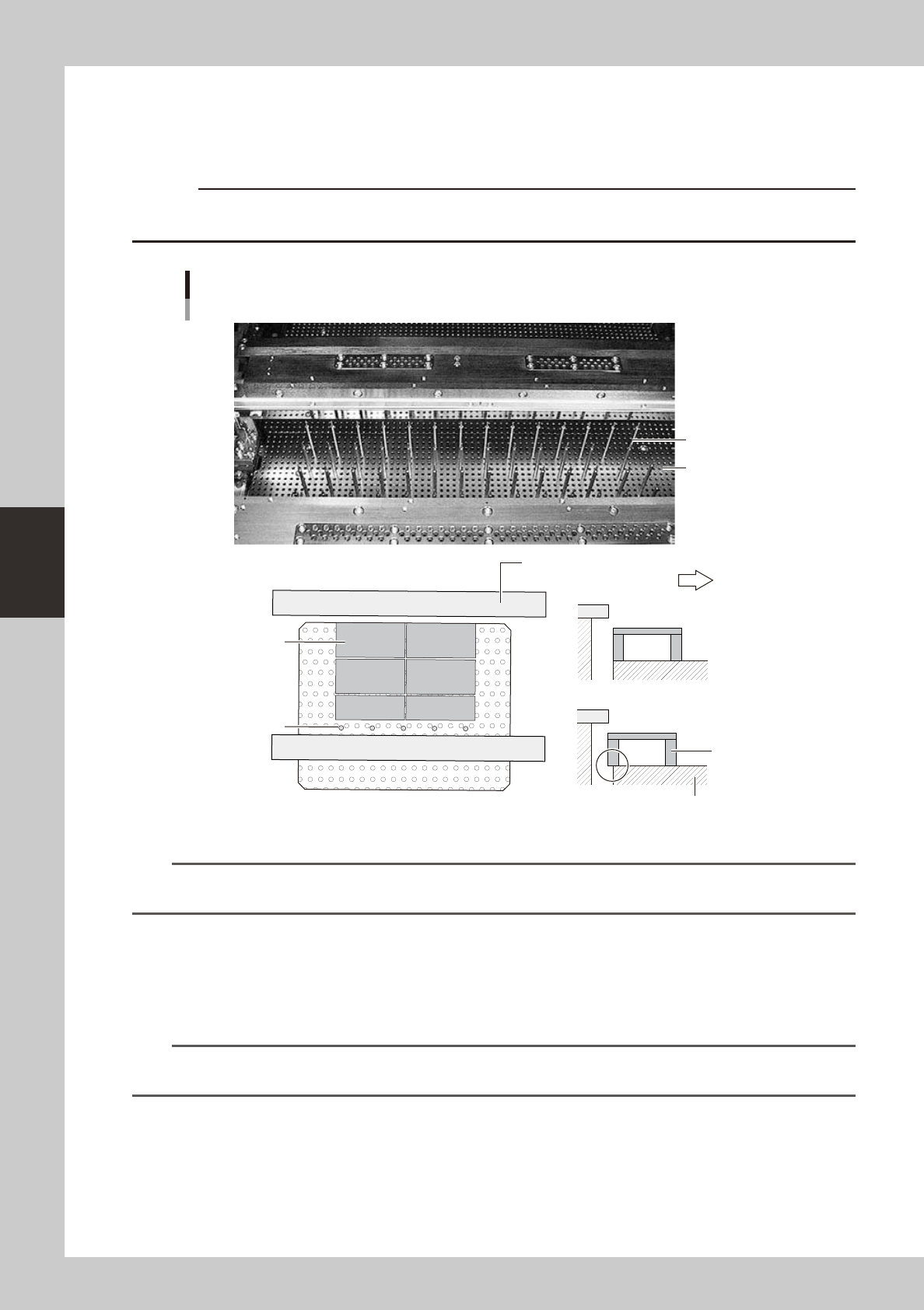
Set the backup pins (or board support jigs).
When the DOOR LOCK lamp turns off, open the safety cover and set the backup jigs on the matrix plate
to match the size of the board to be produced. If using optional board support jigs, they can be used
together with the backup pins.
c
immediately in case of emergency.
OK
NG
Arranging the backup pins
Backup pins
Backup pins
(When board support jigs and backup pins are used together)
Board support jig
Fixed conveyor rail
Board support jig
Machine front side
Matrix plate
Matrix plate
63402-N3-10
n
NOTE
When the backup pin arrangement has been input by pressing the [Backup Pin Pos.] button on the [Print]-[Board] tab
screen, this is convenient to arrange the backup pins. (For more details, see “3. Back pin arrangement” in Chapter 7.)
4
Close the cover and press the [READY] button.
5
Press the [Convey In] button to load a board into the machine.
Follow the instructions that appear on the screen to load a board into the machine. The board is
automatically clamped in the print position.
n
NOTE
When both lanes are used for production, the dialog box for selecting the lane number appears, so select the lane.
The lane currently used in production is grayed out.
6
Check the board clamp status.
1. Press the [SW Prod. Position] button and select “Transfer Check Position”.
2. When the DOOR LOCK lamp turns off, open the cover and touch the board to check for warpage
and backlash.