YSP20_Users_E.pdf - 第168页
5-42 5 Creating and setting the data 4 Check the gr aphic alignment. 1. After closing the teach window, press the [Setup] button and select the [Setup] tab. 2. Press the [Visual Matching] button to open the dialog box fo…
5-41
5
Creating and setting the data
3
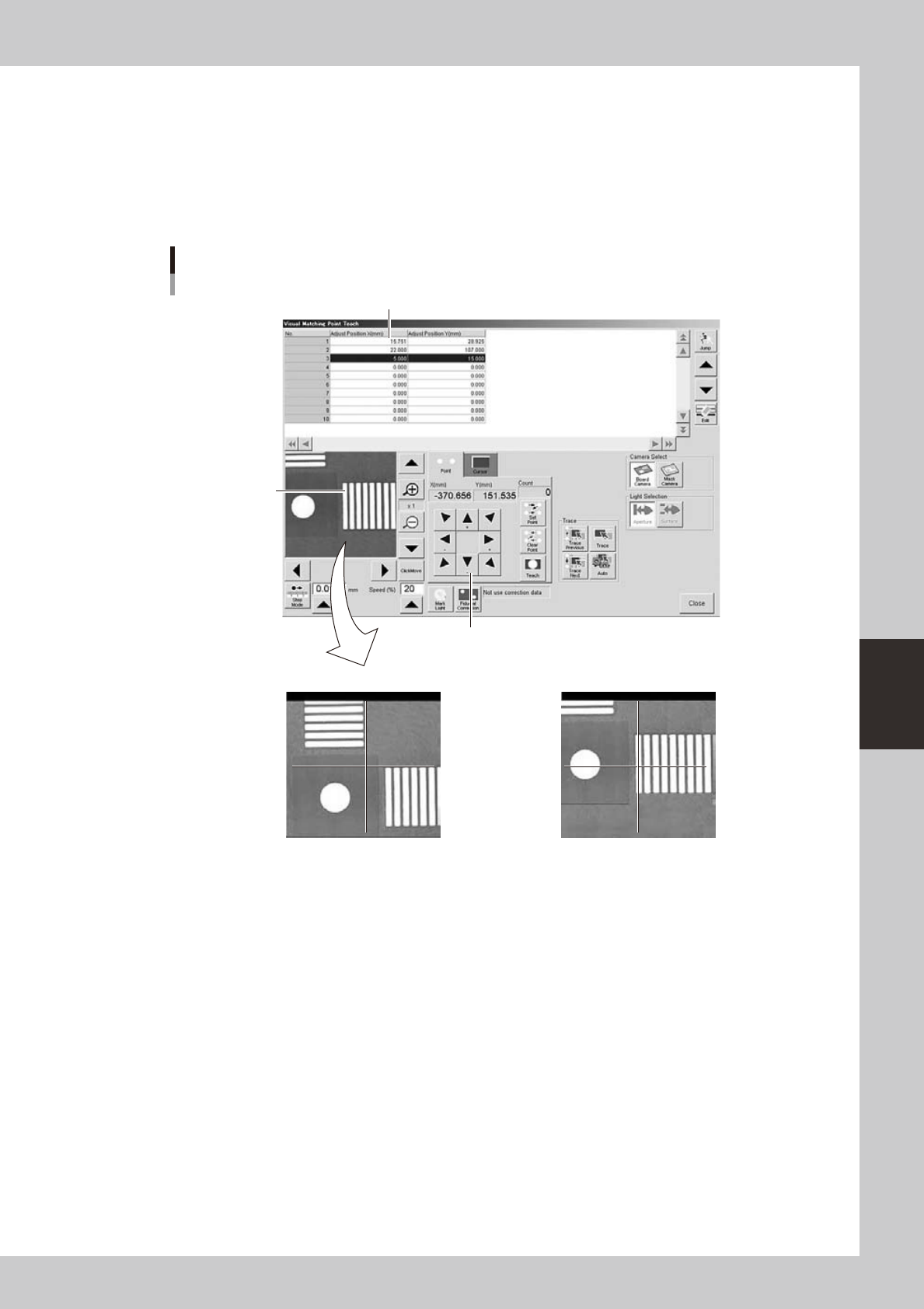
Teach the coordinates for graphic alignment.
1. Press the [Teach] button to open the teach window for graphic alignment.
2. Position the cursor on the first coordinates and press the [Trace] button.
3. Using the arrow keys, align the target coordinates (pad) with the center.
4. Press the [Teach] button to teach the coordinates.
Use the same method to teach the second point.
Teach window for graphic alignment
Arrow keys
NG OK
Pad to be aligned
Alignment coordinates
64542-N3-10
5-42
5
Creating and setting the data
4
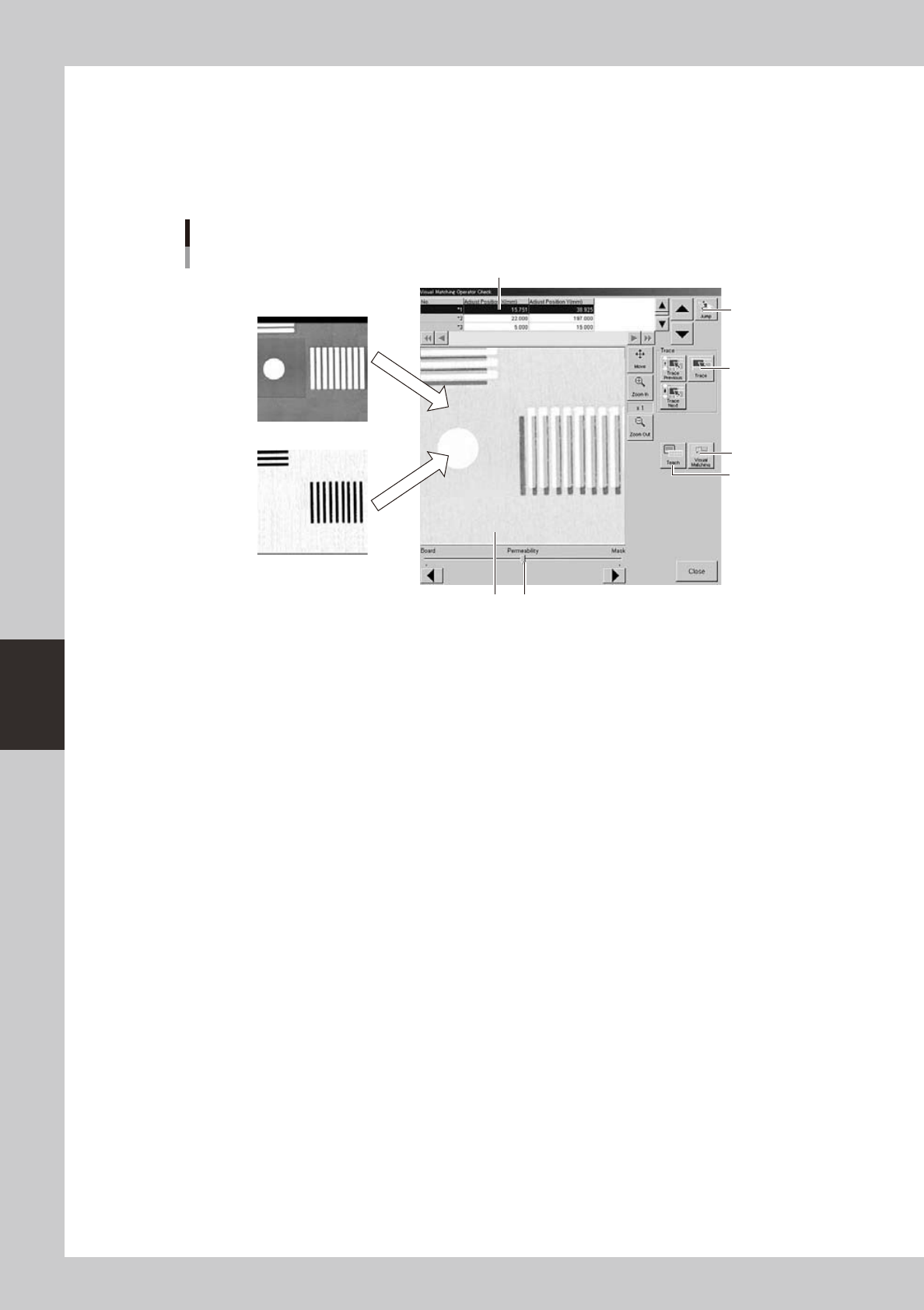
Check the graphic alignment.
1. After closing the teach window, press the [Setup] button and select the [Setup] tab.
2. Press the [Visual Matching] button to open the dialog box for graphic alignment check.
3. The vision monitor in this dialog box shows an overlapped image of the board and mask, so check
the board and mask alignment.
Dialog box for graphic alignment check
Board camera image
Mask camera image
1
4
5
7
6
2 3
64545-N3-00
1: Alignment coordinates
Select the coordinates where you want to check the board and mask alignment. These coordinates should first be set on
the [Print]-[Squeegee] tab screen. (See "5.1 Squeegee detail setting" earlier in this chapter.)
2: Vision monitor
Shows an overlapped image of the board and mask.
The image can be enlarged from 1 to 16 times by pressing the enlarge [ + ] button, or reduced to 1/16 of the original
image by pressing the reduce [ - ] button. With the [Move] button depressed, you can move the image by dragging it with
the mouse.
3: Permeability
The transmittance of the board image and mask image can be adjusted with the slide bar or the arrow buttons.
4: [Teach] button
Opens the teach screen.
5: [Visual Matching] button
Opens the "Visual Matching" screen for making fine position alignments when needed. (See step 5.)
6: [Jump] button
Allows jumping to any desired row in the alignment coordinate list.
7: [Trace] button
Pressing the [Trace] button displays an image of the currently selected alignment coordinates. Pressing the [Trace
Previous] button displays an image of the alignment coordinates one row up from the currently selected coordinates.
Pressing the [Trace Next] button displays an image of the alignment coordinates one row down.
5-43
5
Creating and setting the data
5
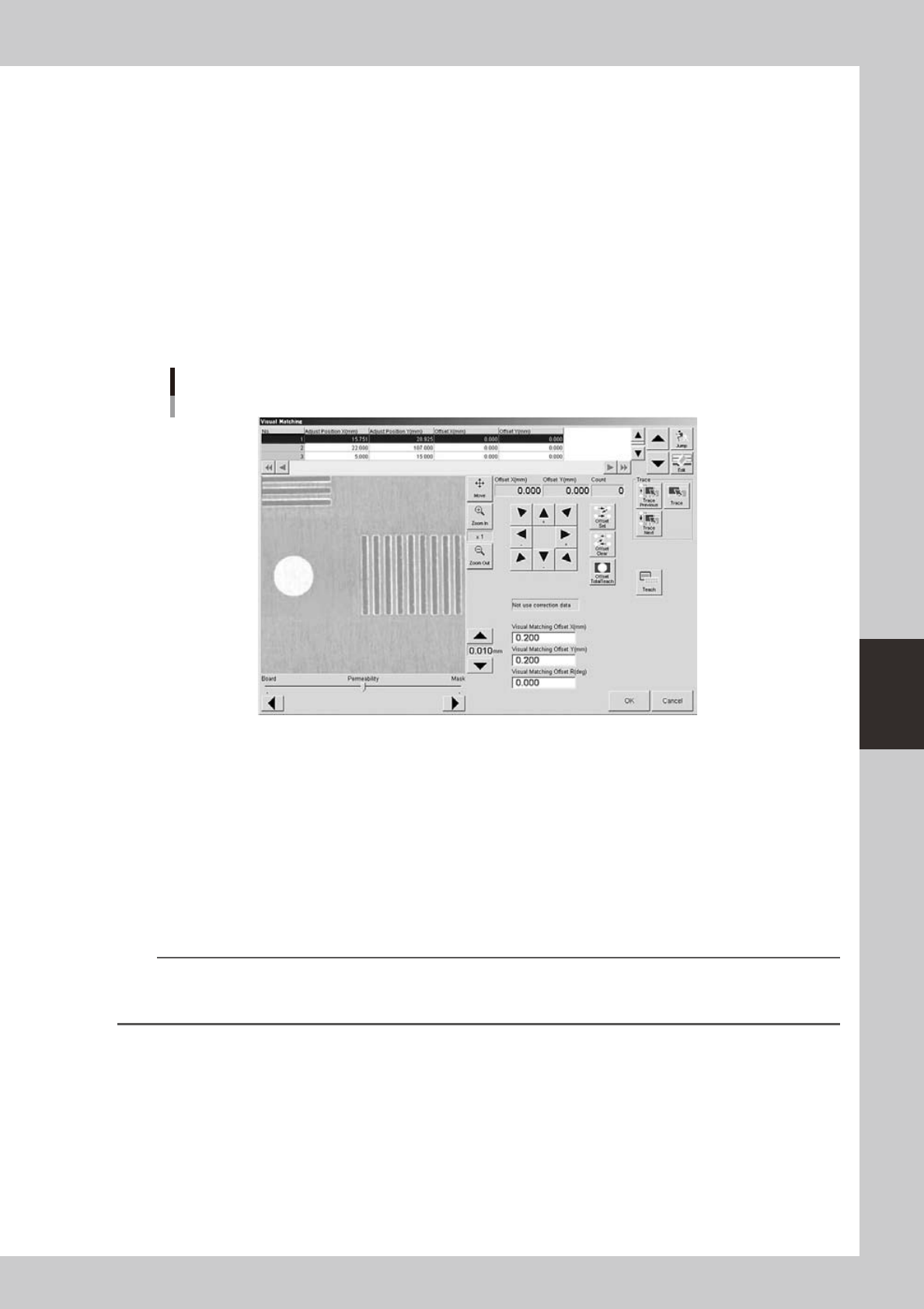
Press the [Visual Matching] button.
If a position offset (deviation) is found by graphic or visual alignment, you can adjust it in the "Visual
Matching" screen that appears when you press the [Visual Matching] button. (Skip this step when no
position offset is found.)
1. While moving the image in the XY directions using the [Arrow] buttons, make fine-alignments until
position offsets are no longer seen. The values in the "Offset X" and "Offset Y" boxes just above the
[Arrow] buttons change as you move the image.
2. After aligning the position, press the [Offset Set] button.
The number "1" appears in the "Count" box.
3. When you want to make alignments at other coordinates, select the coordinates and repeat the
same procedure.
The number in the "Count" box increments each time an alignment is made ([Offset Set] button is
pressed).
"Visual Matching" screen
64546-N3-10
6
When finished making alignments at the necessary coordinates, press the [Offset
Total Teach] button.
The offset amount for the entire board is then calculated based on the adjusted offset values and the
results displayed in the "Visual Matching Offset X", "Visual Matching Offset Y" and "Visual Matching Offset
R" boxes in the lower part of the screen.
Press the [Offset Clear] button if you want to clear the offset amount and retry from the beginning.
7
Press the [OK] button to update the offset amount.
The offset amount calculated here will be entered in the "F. Mask Offset XYR" and "B. Mask Offset XYR" in
the squeegee data. If you do not want to update the offset amount, press the [Cancel] button.
n
NOTE
If you want to align the printing position with a point other than the center of the board in order to compensate for
board or mask expansion, make graphic alignments after updating the offset by adjusting the center position and
rotational deviations.
8
Close the dialog box for graphic alignment.
After closing the dialog box, follow the message that appears and unload the board.